
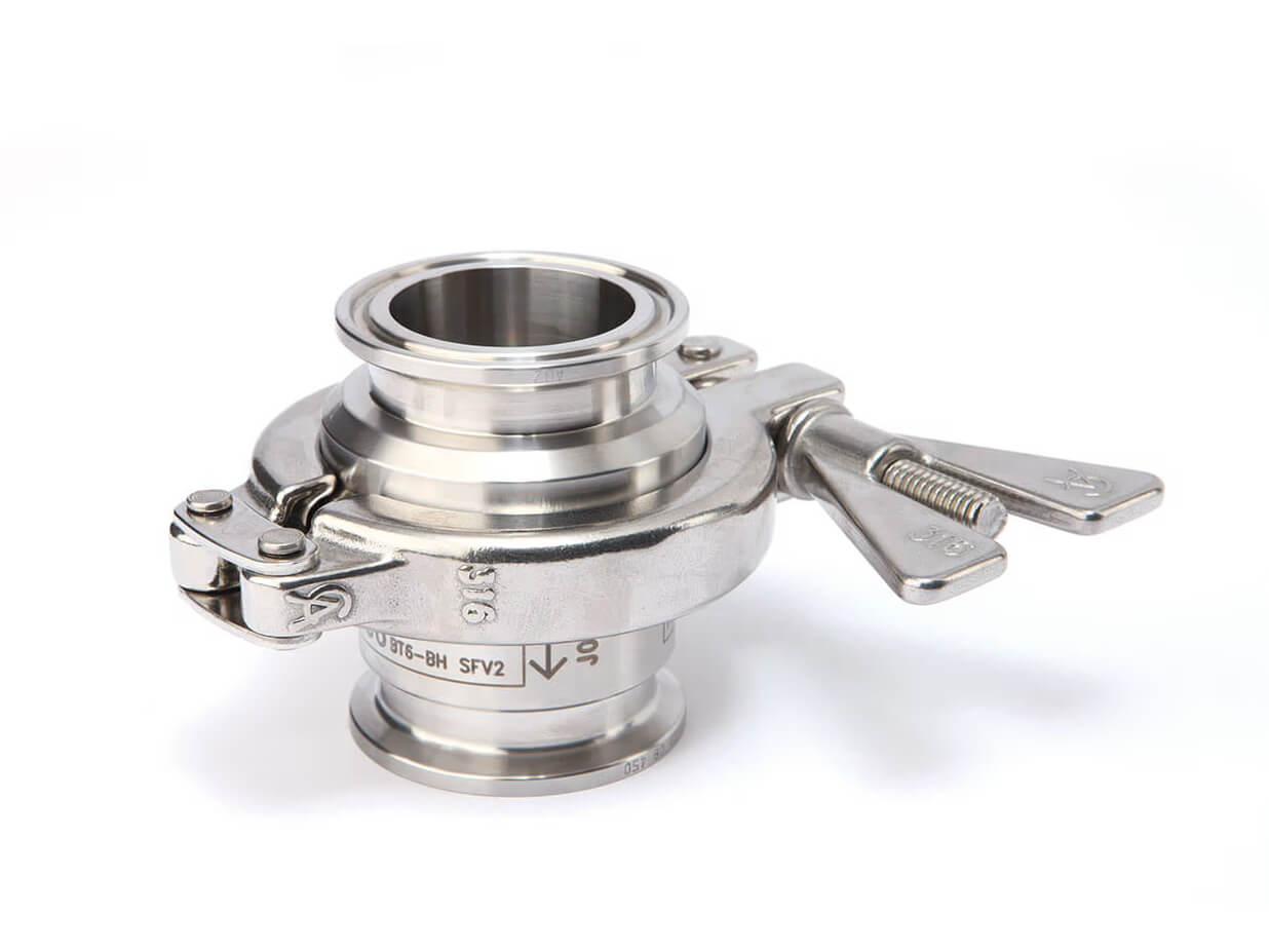
BT6-BH high-capacity sanitary balanced pressure thermostatic steam trap
Spirax Sarco BT6-BH is the high-capacity type of a sanitary balanced pressure thermostatic steam trap platform for clean, chemical-free and pure steam services. It is intended for condensate removal where low retention, drainability and a hygienic wetted construction matter as much as the nominal connection. The documented application range includes sterile steam barriers, block-and-bleed installations, steam main drainage, and CIP/SIP duties on vessels, reactors and process lines.
The high-capacity designation matters during selection. A trap should be matched to the condensate load and the differential pressure available at the actual operating point, not selected from connection size alone. The official capacity chart identifies the BH curves for the target type. Final sizing should also account for start-up conditions, operating pressure, return-line conditions and any restriction from the selected sanitary clamp or gasket.
Why the BT6-BH is suited to hygienic steam drainage
The BT6-BH uses a 316L stainless steel, crevice-free body with a 15-degree angled seat. This geometry is intended to support full drainability, reducing places where condensate can remain after drainage or cleaning. In a clean-steam installation, that detail affects more than heat transfer: retained liquid can make cleaning, drying and repeatable operation harder to manage. The body, capsule element and seal construction are documented in the technical section, while the final material and connection schedule should be checked against the ordered configuration.
Its balanced pressure thermostatic element responds to condensate temperature. During cold and start-up conditions the capsule is open, allowing air, condensate and CIP fluid to leave the system. As the system approaches steam temperature, the fill fluid expands and the valve closes near steam temperature to reduce live-steam loss while maintaining drainage. The standard element is specified to open within 2 °C (4 °F) nominal sub-cooling of steam saturation temperature at 50 mm (2 inch) above the trap and at pressures below 2.4 bar g (35 psi g) in typical operating conditions. That statement is conditional: operating pressure, installation and ambient conditions affect actual performance.
Construction, finish and configuration choices
BT6-BH construction is designed around a sanitary service boundary rather than an industrial trap body adapted after manufacture. The documented wetted body and capsule element use 316L stainless steel. The safety clamp is 316 stainless steel and the seal is a PTFE plus 316L stainless-steel composite gasket. Internal surfaces are listed with a typical 0.6 micrometre Ra finish and external surfaces with 1.0 micrometre Ra. Mechanical and electropolishing to 0.375 micrometre Ra is available as an option, so a project specification should state the required finish instead of assuming the optional grade.
Connection choices are listed across sanitary clamp and tube-ended standards. The technical information covers ASME BPE, ISO 1127 and DIN 32676 sanitary clamp families, plus DIN 11866, DIN 11850 and ISO 1127 tube-ended families. Available sizes and standard variations are shown in the technical table that follows. The SSP list and the final order confirmation control which connection type is available for the selected size and market. A fixed bleed can also be specified for fail-open operation. Where food-contact service is being considered, the Food+ documentation and the required cleaning-in-place process must be confirmed for the complete system.
Pressure, temperature and capacity checks
The documented BT6-BH body design condition is PN10. The technical data give a maximum allowable pressure of 10 bar g at 140 °C, a maximum allowable temperature of 177 °C at 9.2 bar g, a maximum operating pressure for saturated steam of 6 bar g and a maximum operating temperature of 165 °C at 6 bar g. The minimum allowable temperature is -10 °C and the minimum operating temperature is 0 °C. The product is documented as suitable for full vacuum conditions, while the 15 bar g cold hydraulic test pressure is a test limit, not an operating rating.
These values form an operating envelope rather than independent numbers that can be combined freely. Sanitary clamps and gaskets can reduce the permitted pressure or temperature, and the shaded regions of the official pressure/temperature chart must be respected. The high-capacity BH curves in the ISO 7842 chart should be read at the available differential pressure and the required condensate state. A Spirax Sarco BT6-BH selection should be checked across cold start-up, normal running and cleaning before the model and connection configuration are released for order.
BT6-BH applications and selection boundaries
Typical duties are those where condensate must be removed without undermining hygienic design: clean-steam mains drainage, sterile barriers, block-and-bleed arrangements, and the cleaning or sterilisation cycles of vessels and reactors. The trap is one part of that system. The upstream process still needs suitable isolation, pressure protection, safe discharge routing and a layout that prevents condensate from backing up into equipment. A cooling leg is called for in the installation instructions, and the body must be installed with downward flow in a vertical line so it can self-drain.
For broader product selection, use the steam trap selection guide to compare operating principles and system duties. When the clean-steam system also needs dedicated removal of non-condensable gases, the AVM7 hygienic air vent is a relevant complementary selection route. The BT6-B family page can be used as the broader family reference when checking the relationship between the high-capacity target type and the family-level documentation. These links support different selection tasks; none changes this page's single-model scope.
Installation, operation and maintenance planning
Before installation, verify the nameplate, intended fluid, materials, pressure and temperature limits, flow direction and connection standard. Remove protective covers where appropriate, protect machined surfaces and avoid imposing external pipe stress on the body. The trap must not be exposed to superheat conditions. The outlet should be routed to a safe location; the installation instructions warn that atmospheric discharge may be at 100 °C. Build pressure slowly during commissioning and check alarms or protective devices after installation or maintenance.
Maintenance planning should leave enough access to remove the sanitary clamps and service the capsule element, seal and outlet body with seat. Isolate both supply and return lines, vent pressure gradually to atmosphere and allow the assembly to cool to 60 °C or below before removing the body clamp. Reassemble with a new seal, tighten the clamps and check for leaks. The available spares are limited to the capsule element assembly, seal, and outlet body including the seat; order requests should state the size and the BT6-BH type.
BT6-BH enquiry checklist
- Confirm clean or pure steam service, condensate load, start-up case and the differential pressure available at the trap.
- Confirm the vertical, downward-flow installation and the cooling-leg arrangement before finalising the pipe route.
- Specify the sanitary clamp or tube-ended standard, nominal size, gasket/clamp limitations and required surface finish.
- Check the complete pressure/temperature envelope, return-line backpressure, safe discharge route and any superheat exposure.
- State certification, traceability, passivation, Food+ documentation or fixed-bleed requirements at the time of order where applicable.
For a Spirax Sarco BT6-BH enquiry, retain the operating data with the model, connection standard and finish requirement. This gives the final selection review enough information to distinguish high-capacity duty from a nominal-size match and to keep the hygienic installation within its documented limits.
Description and target type
The BT6-BH is the high-capacity type of the sanitary balanced pressure thermostatic steam trap family. It is designed to remove condensate from clean, chemical-free and pure steam applications with minimal condensate retention.
Documented applications include sterile steam barriers, block-and-bleed installations, steam main drainage, and CIP/SIP of vessels, reactors and process lines. The product is manufactured with a crevice-free 316L body design and a 15-degree angled seat to support full drainability.
The standard element is designed to open within 2 °C (4 °F) nominal sub-cooling of steam saturation temperature at 50 mm (2 inch) above the trap and at pressures below 2.4 bar g (35 psi g) in typical operating conditions. Actual operating performance may be affected by operating pressure, installation and ambient conditions.
Options and surface finish
- Internal surfaces: 0.6 micrometre Ra (25 micro-inch Ra, ASME BPE SF2).
- External surfaces: 1.0 micrometre Ra (40 micro-inch Ra).
- Mechanical and electropolishing to 0.375 micrometre Ra (15 micro-inch Ra, ASME BPE SF4).
- Fixed bleed for fail-open operation.
The body surface finish is measured to ISO 4287-1997 and ISO 4288-1997. Each trap is individually packaged in an ISO Class 7 clean environment with protective end caps and a sealed protective plastic bag.
Standards, compliance and certification
The source sheet states that the BT6-B design is built in general accordance with ASME BPE and complies with the European Pressure Equipment Directive 2014/68/EU. For the Food+ range covered by the source, it also states compliance with EC1935:2004 for food-contact materials and EC2023:2006 on good manufacturing practice for materials and articles intended to come into contact with food. Seal material documentation refers to FDA CFR Title 21 paragraph 177.1550, USP Class VI biological reactivity testing in vitro <87> and in vivo <88> at 121 °C (250 °F) for one hour, ADI-free materials and processes, TSE/BSE-free certification, and full material lot traceability.
Available certification and inspection documents include EN 10204 3.1 full validation pack, pressure-retaining-parts material certification, wetted-parts material certification for element spares, specific or typical internal surface finish records, FDA/USP/ADI statements, a TSE-BSE statement, Food+ declaration of compliance where applicable, a BS EN ISO 14644-1:2015 Class 7 clean-room declaration, passivation certificate and typical test report. Requirements must be stated at order placement and some are chargeable.
Sizes and pipe connections
The following source matrix covers sanitary clamp-ended and tube-ended connection families. It is a standards and size reference, not a promise that every combination is available in every market. Consult the SSP list and confirm the final connection with the order.
| Connection family | Standard | Issue | Type or series | Sizes listed in source |
|---|---|---|---|---|
| Sanitary clamp-ended variants | ASME BPE | - | Type A | 1/2 inch, 3/4 inch |
| ASME BPE | - | Type B | 1 inch, 1 1/2 inch | |
| ISO 1127 | 1997 | Series 1 | DN25, DN40 | |
| ISO 1127 | 1997 | Variations | DN15, DN20 | |
| DIN 32676 | 2001-02 | Series 2 | DN15, DN20, DN25, DN40 | |
| DIN 32676 | 2009-05 | Series A | DN15, DN20, DN25, DN40 | |
| DIN 32676 | 2009-05 | Series B | DN8, DN10, DN15, DN20, DN25, DN32, DN40 | |
| DIN 32676 | 2009-05 | Series C | 1/2 inch, 3/4 inch, 1 inch, 1 1/2 inch | |
| Tube-ended variants | DIN 11866 | 2016-11 | Series A | DN15, DN20, DN25, DN40 |
| DIN 11850 | 1999-01 | Series 2 | DN15, DN20, DN25, DN40 | |
| ISO 1127 | 1997 | Series 1 | DN15, DN20, DN25, DN40 |
The Food+ range is listed as available with ASME BPE connections. For other connection requirements, consult Spirax Sarco.
Materials
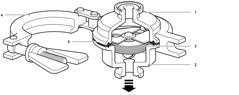
| No. | Part | Material |
|---|---|---|
| 1 | Body, inlet | Stainless steel, 316L (1.4404) |
| 2 | Body, outlet | Stainless steel, 316L (1.4404) |
| 3 | Capsule element | Stainless steel, 316L (1.4404) |
| 4 | Safety clamp | Stainless steel, 316 (1.4401) |
| 5 | Seal | PTFE and 316L (1.4404) stainless-steel composite gasket |
Pressure/temperature limits (ISO 6552)
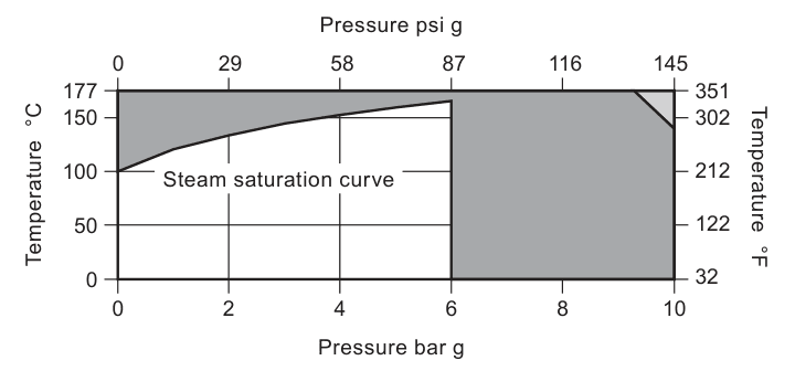
For hygienic or sanitary clamp ends, the maximum pressure and temperature may be restricted by the gasket or sanitary clamp used. Consult the final connection specification.
| Body design condition | PN10 |
|---|---|
| PMA maximum allowable pressure | 10 bar g @ 140 °C (145 psi g @ 284 °F) |
| TMA maximum allowable temperature | 177 °C @ 9.2 bar g (351 °F @ 139 psi g) |
| Minimum allowable temperature | -10 °C (14 °F) |
| PMO maximum operating pressure for saturated steam | 6 bar g (87 psi g) |
| TMO maximum operating temperature | 165 °C @ 6 bar g (329 °F @ 87 psi g) |
| Minimum operating temperature | 0 °C (32 °F) |
| Vacuum service | Suitable for use under full vacuum conditions |
| Maximum cold hydraulic test pressure | 15 bar g (218 psi g) |
The hydraulic test value is a test pressure, not an operating rating. Follow IM-P180-31 for the required removal of internals and gasket substitution before hydraulic testing.
Capacity chart (in accordance with ISO 7842)
The chart below is the official source graph for condensate, cold-water and hot-water capacity against differential pressure. The BH annotations identify the high-capacity curves for the target type. Read the curve at the actual differential pressure and required condensate condition; do not treat a nominal connection as a capacity value.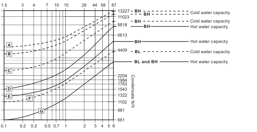
| Chart marker | Size association shown by the source |
|---|---|
| A | DN25 (1 inch), DN32 and DN40 (1 1/2 inch) |
| B | DN20 (3/4 inch) |
| C | DN8, DN10 and DN15 (1/2 inch) |
| D | DN25 (1 inch), DN32 and DN40 (1 1/2 inch) |
| E | DN20 (3/4 inch) |
| F | DN8, DN10, DN15 (1/2 inch), DN20 (3/4 inch), DN25 (1 inch), DN32 and DN40 (1 1/2 inch) |
| G | Small-size high-capacity BH curve group shown in the source chart; use the final size/type selection sheet for the ordered configuration. |
Approximate dimensions
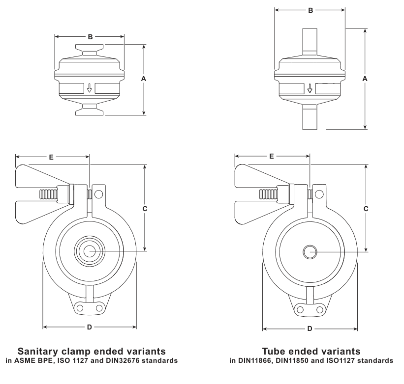
| Connection family | Sizes or standard group | A | B | C | D | E | Weight |
|---|---|---|---|---|---|---|---|
| Sanitary clamp-ended | ASME BPE Types A and B, ISO 1127, DIN 32676 Series 2, A and C variants | 65 mm (2.6 inch) | 64 mm (2.5 inch) | 71.5 mm (2.8 inch) | 77 mm (3 inch) | 61 mm (2.4 inch) | 1 kg (2.2 lb) maximum |
| Sanitary clamp-ended | DIN 32676 Series B | 65 mm (2.6 inch) | 64 mm (2.5 inch) | 71.5 mm (2.8 inch) | 77 mm (3 inch) | 61 mm (2.4 inch) | 1 kg (2.2 lb) maximum |
| Tube-ended | DIN 11866 Series A, DIN 11850 Series 2, ISO 1127 Series 1 | 92 mm (3.6 inch) | 64 mm (2.5 inch) | 71.5 mm (2.8 inch) | 77 mm (3 inch) | 61 mm (2.4 inch) | 1 kg (2.2 lb) maximum |
Installation note and operation
For self-draining operation, the trap is designed to be installed in a vertical line with flow downward. Check the flow arrow on the body. Installation should include a suitable cooling leg to avoid condensate backup into process equipment under normal operating conditions. Do not expose the capsule element to superheat conditions, and handle all components carefully to avoid damaging the machined surfaces.
The stainless-steel capsule is filled with a WFI temperature-sensing fluid. During cold or start-up conditions it is fully open, allowing large volumes of air, condensate and/or CIP fluid to drain. As the system approaches steam temperature, the fill fluid expands and the valve closes the trap near steam temperature to reduce live-steam loss while maintaining efficient drainage.
Ordering example
Example wording from the source: one 1/2 inch BT6-BH sanitary balanced pressure thermostatic steam trap with a self-draining body, sanitary clamp ends to meet ASME BPE requirements, suitable for pressure up to 6 bar g, internal surface electropolished to 0.375 micrometre Ra (15 micro-inch Ra, ASME BPE SF4), and material certification to EN 10204 3.1 for pressure-containing parts.
State the size, connection standard, pressure and temperature duty, required finish, certification and any fixed-bleed or Food+ documentation requirement at order placement. The separate installation and maintenance instructions contain the full safety, commissioning and service procedure.
Installation and Maintenance Guide
- Safety information
- General product information
- Installation
- Commissioning
- Operation
- Spare parts and maintenance
- Disposal and returns
These instructions apply to the BT6-B sanitary trap family and are used here for the BT6-BH high-capacity type identified in TI-P180-30.
1. Safety information
Safe operation can only be guaranteed when the product is installed, commissioned, used and maintained by qualified personnel in compliance with the operating instructions. General pipeline and plant-construction safety rules, suitable tools and safety equipment also apply.
1.1 Intended use
Check these instructions, the nameplate and TI-P180-30 to confirm suitability for the intended application. The source document identifies the product as designed for steam, air or water/condensate in Group 2 of the European Pressure Equipment Directive. Contact Spirax Sarco before considering another fluid.
Check material compatibility, maximum and minimum pressure and temperature, and the consequences of malfunction. If the product limits are lower than the system limits, provide a safety device to prevent overpressure or overtemperature.
1.2 Access and lighting
Provide safe access and, where necessary, a guarded working platform before work starts. Arrange suitable lifting equipment if required and provide adequate lighting for detailed work.
1.3 Pipeline contents and surroundings
Consider what is in the pipeline, what may previously have been in it, flammable or hazardous substances, extreme temperatures, explosion-risk areas, lack of oxygen, dangerous gases, hot surfaces, fire hazards, excessive noise and moving machinery.
1.4 The complete system
Consider whether isolation or electrical isolation could put another part of the system or personnel at risk. Do not make vents, protective devices, controls or alarms ineffective. Operate isolation valves gradually to avoid system shocks.
1.5 Pressure and temperature
Isolate pressure and vent it safely to atmosphere. Consider double isolation, double block and bleed, and locking or labelling closed valves. A gauge reading of zero does not prove that the system is depressurised. Allow temperature to normalise after isolation to avoid burns.
If conditional Viton parts have seen approximately 315 °C or more, hydrofluoric acid may form. If PTFE parts have seen approximately 260 °C or more, toxic fumes may be released. Follow the source safety instructions, enforce the stated no-smoking rule for PTFE handling and prevent contact or inhalation hazards.
1.6 Tools, clothing and permits
Have suitable tools and consumables ready and use genuine replacement parts. Assess the need for protective clothing for chemicals, temperature, radiation, noise, falling objects and eye or face hazards. Work must be carried out or supervised by a competent person, with the site permit-to-work system followed.
1.7 Handling, residual heat and freezing
Assess manual-handling risks and use an appropriate method. The external surface may be very hot and can exceed 177 °C at maximum permitted conditions. Take care when removing the trap. Protect non-self-draining systems from frost damage where freezing temperatures are possible.
For Food+ food-contact systems, the source instructions require an appropriate CIP cycle before first use to minimise the risk of non-intentionally added substances. Confirm the relevant declaration and complete process qualification for the installation.
2. General product information
The BT6-BH is the high-capacity sanitary balanced pressure thermostatic steam trap type. It removes condensate from clean chemical-free and pure steam applications with minimal condensate retention. Applications include sterile steam barriers, block-and-bleed installations, steam main drainage and CIP/SIP of vessels, reactors and process lines.
The crevice-free 316L body includes a 15-degree angled seat for full drainability. The standard temperature-sensitive capsule is designed to open within 2 °C nominal sub-cooling of steam saturation temperature at 50 mm above the trap and below 2.4 bar g in typical conditions. Actual performance depends on operating pressure, installation and ambient conditions.
Options include a fixed bleed for fail-open operation and mechanical/electropolishing to 0.375 micrometre Ra. Surface, material, connection, certification and Food+ requirements must be confirmed against the ordered configuration. Sanitary clamps or gaskets may restrict the maximum pressure and temperature. The product is documented as suitable for full vacuum conditions, but the actual connection and system must still be checked. Consult the SSP list for available types and confirm the final connection, size, clamp and gasket before installation. Fittings, clamps and gaskets for pipe-end connections are not supplied.2.1 Pre-installation pressure and temperature check
Condition Source limit Body design condition PN10 Maximum allowable pressure 10 bar g at 140 °C Maximum allowable temperature 177 °C at 9.2 bar g Minimum allowable temperature -10 °C Maximum operating pressure for saturated steam 6 bar g Maximum operating temperature 165 °C at 6 bar g Minimum operating temperature 0 °C Hydraulic test pressure 15 bar g maximum cold test pressure; follow Section 3.5 2.2 Sizes and pipe connections
Connection family Standard / issue Type or series Sizes listed Sanitary clamp-ended variants ASME BPE Type A 1/2 inch, 3/4 inch ASME BPE Type B 1 inch, 1 1/2 inch ISO 1127 / 1997 Series 1 DN25, DN40 ISO 1127 / 1997 Variations DN15, DN20 DIN 32676 / 2001-02 Series 2 DN15, DN20, DN25, DN40 DIN 32676 / 2009-05 Series A DN15, DN20, DN25, DN40 DIN 32676 / 2009-05 Series B DN8, DN10, DN15, DN20, DN25, DN32, DN40 DIN 32676 / 2009-05 Series C 1/2 inch, 3/4 inch, 1 inch, 1 1/2 inch Tube-ended variants DIN 11866 / 2016-11 Series A DN15, DN20, DN25, DN40 DIN 11850 / 1999-01 Series 2 DN15, DN20, DN25, DN40 ISO 1127 / 1997 Series 1 DN15, DN20, DN25, DN40
3. Installation
Before installation, observe all safety information in Section 1. Refer to the nameplate and TI-P180-30 and confirm material suitability, pressure and temperature limits, installation situation and direction of fluid flow.
- Prepare the connections. Remove protective covers from connections and protective film from nameplates where appropriate before high-temperature service.
- Set the direction. The BT6-BH is designed for a vertical line with flow downward so the body can self-drain. Check the flow arrow on the body. Do not expose the capsule element to superheat.
- Provide condensate drainage space. Include a suitable cooling leg to avoid condensate backup into process equipment under normal operating conditions.
- Fit the sanitary clamp. Handle the body and element carefully so machined surfaces are not damaged. Do not overtighten the clamp: take up slack and tighten the nut by no more than half a turn maximum, as overtightening may spread or extrude the seal into the element frame.
- Prepare for hydraulic testing. For the maximum 15 bar g cold hydraulic test, remove the internals and substitute the standard gasket with a Viton gasket. When swapping the gasket or removing internals, retighten the clamp to 50 lbf-in (5.65 N m) as specified in the source instructions.
- Route discharge safely. If the trap discharges to atmosphere, route it to a safe place; the discharged fluid may be at 100 °C (212 °F).
The installer remains responsible for minimising external pipe stresses and for providing safe access, lighting, handling arrangements and personal protection.
4. Commissioning
After installation or maintenance, confirm that the system is fully functioning and test alarms or protective devices. Build pressure slowly, as rapid pressurisation can damage sensitive equipment.
5. Operation
The operating element is a stainless-steel capsule filled with WFI temperature-sensing fluid. During cold or start-up conditions the capsule is fully open and allows air, condensate and/or CIP fluid to drain. As the system approaches steam temperature, the fill fluid expands and the valve closes the trap near steam temperature to prevent live-steam loss while maintaining efficient system drainage.
6. Spare parts and maintenance
6.1 Available spare parts
The source drawing shows available spares in solid outline. Parts drawn in grey are not supplied as spares.
| Spare | Drawing reference |
|---|---|
| Capsule element assembly | 3 and 5 |
| Seal | 5 |
| Body outlet including seat | 2 |
Order spares using the description in the source list and state the size and type of trap. Example: one capsule element assembly for a 1/2 inch BT6-BH sanitary balanced pressure thermostatic steam trap.
6.2 Maintenance procedure
- Isolate the supply and return lines, allow pressure to normalise slowly to atmosphere and let the assembly cool.
- Do not remove the body clamp until the trap has cooled to 60 °C or below; damage to the capsule element assembly can occur above this temperature.
- Remove the sanitary clamps from the pipeline and remove the whole trap from the pipeline.
- Remove the body sanitary clamp. Remove the inlet and outlet body including the seat, seal and capsule element assembly for cleaning or replacement.
- Reassemble with a new seal and the valve head positioned to close onto the seat orifice. Replace and tighten the sanitary clamps.
- Return the trap to service, check for leaks and retighten as necessary.
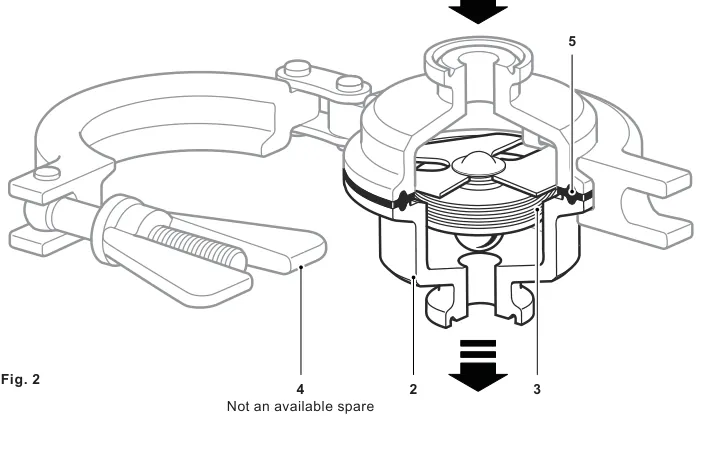
On occasions the gasket may bond to the metal parts. Do not pull or lever the welded capsule. Gently prise the gasket from the valve body as shown in the source maintenance sequence, then reassemble with a new seal.
7. Disposal and returns
Unless otherwise stated, the product is recyclable and no ecological hazard is anticipated when it is disposed of with due care and in accordance with local regulations. PTFE waste must be kept separate and disposed of by an approved method, not incinerated. Follow the current product-compliance information and local requirements.
When returning a product, provide written information about contamination residues, mechanical damage, hazards and the precautions required, including relevant safety data for hazardous substances.