
Back to the TDS blowdown controls family
Return to the wider TDS blowdown controls route when the project is still comparing controllers, probes and blowdown valve arrangements.
Boiler controls and systems > TDS blowdown controls
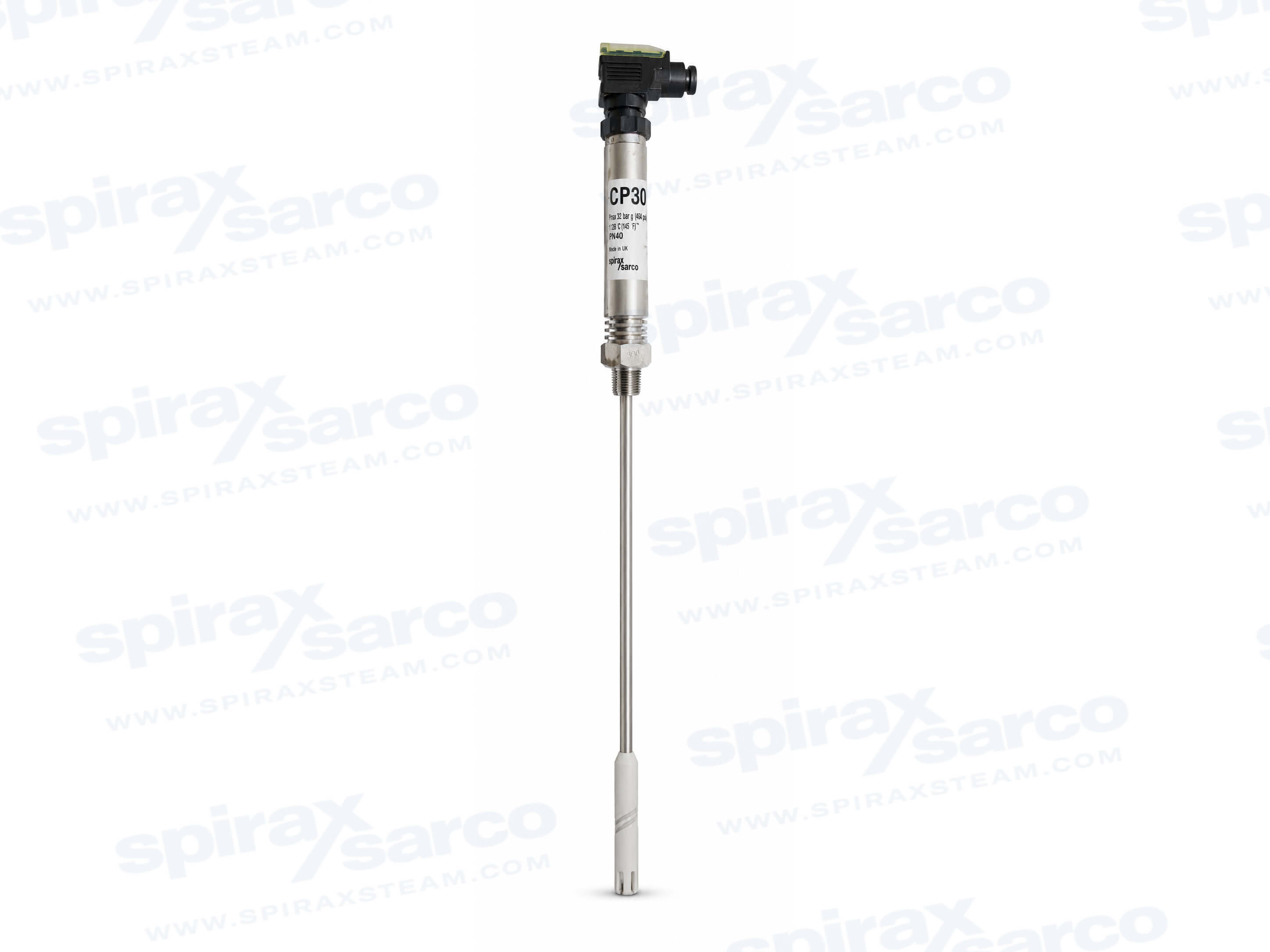
CP30 Conductivity Probe
The Spirax Sarco CP30 is a cut-to-length conductivity probe for steam boiler conductivity or total dissolved solids (TDS) measurement and blowdown monitoring or control, with 300, 500, 1000 and 1500 mm nominal electrode lengths and standard 3/8 inch BSP or UL 1/2 inch NPT connection options.
Quick facts
The Spirax Sarco CP30 conductivity probe provides the sensing point for boiler water conductivity or total dissolved solids (TDS) monitoring. Used with a compatible blowdown controller, it gives the control system a repeatable indication of boiler water condition so that an automatic TDS blowdown arrangement can monitor and control dissolved solids. The Spirax Sarco CP30 is therefore a measurement component within a boiler control system, not a standalone controller or blowdown valve.
Its design is intended for steam boiler applications where the probe must be installed at a representative point in the boiler water. The sensing electrode can be cut to the exact insertion length required before installation, while the probe body and connection arrangement provide a practical route into a probe elbow, a screwed flange or a suitable boiler connection. This combination makes CP30 useful when the installation geometry is known but the final electrode penetration still needs to be matched to the vessel.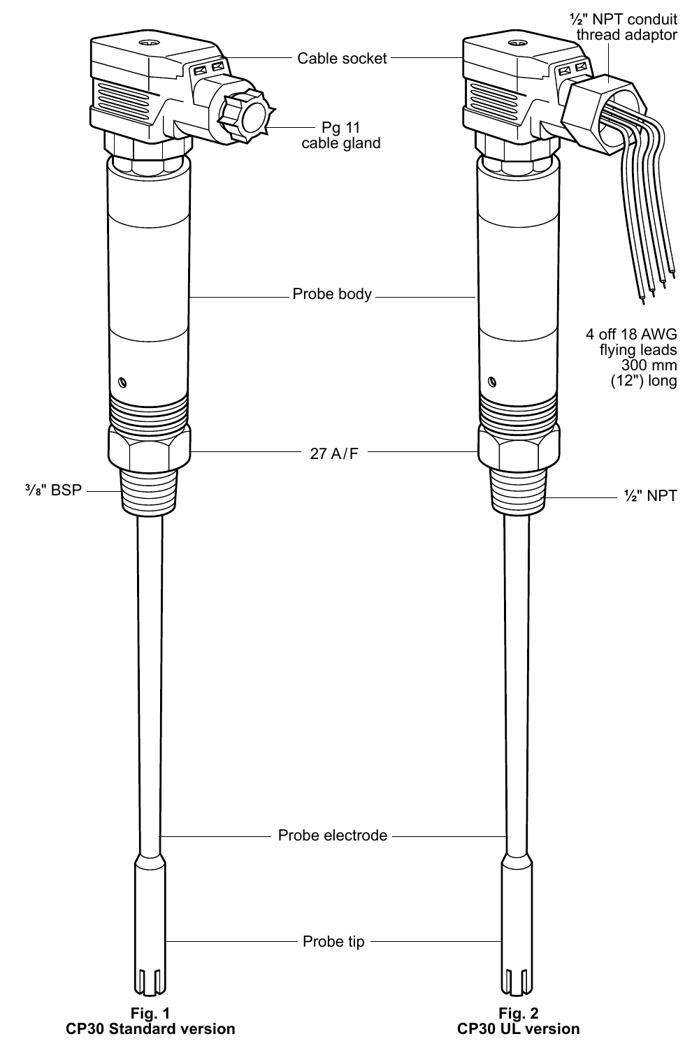
Conductivity is used as a measurable indication of the dissolved material in boiler water. In a TDS control system, the CP30 senses the water and passes the measurement to the selected controller. The controller and blowdown valve package then provide the wider monitoring or control function. The probe should be selected as part of that complete arrangement, with the controller, boiler connection, installation position and blowdown equipment considered together.
The current CP30 installation instructions identify the BC3100, BC3200, BC3210, BC3150 and BC3250 blowdown controllers as compatible controllers with a probe-cleaning facility. Probe conditioning can help reduce the effect of scale on sensing, but it is not a replacement for a suitable boiler water treatment regime. If scale forms on the probe, the boiler should also be treated as a potential scaling location and the water treatment arrangement reviewed by a competent specialist.
For projects still defining the control package, use the TDS blowdown controls family route first. When the controller choice is the remaining question, the existing product route provides direct comparison points for the BC3150 boiler blowdown controller and BC3250 boiler blowdown controller.
The wetted construction combines austenitic stainless steel and PTFE. The technical information identifies the body as austenitic stainless steel Type 316Ti, the probe tip as ASTM A276 316L stainless steel, and the probe-tip sleeving and shroud as PTFE. The internal spring is austenitic stainless steel. These materials define the part of the product that is exposed to boiler water and should be checked against the actual water-treatment chemistry and application conditions before ordering.
The standard CP30 is supplied with a DIN 43650 cable socket and Pg11 cable gland. Its probe connection is a 3/8 inch BSP taper arrangement. A UL version is available with a 1/2 inch NPT connection, a conduit thread adaptor and four 18 AWG flying leads. The technical sheet states that this UL version is approved to UL61010 and is not CE marked. Regional approval, wiring practice and the required connection standard therefore need to be confirmed rather than inferred from the probe length alone.
The probe is supplied in four nominal electrode lengths: 300 mm, 500 mm, 1000 mm and 1500 mm. Each nominal length is a starting point for site selection; the electrode is cut to the required length before installation. The PTFE probe tip is retained by an internal spring, so the cutting and tip-refitting procedure in the installation instructions must be followed by qualified personnel. The exact insertion length should be set from the boiler connection, internal geometry, required immersion and clearance from internal tubes.
CP30 can be installed in a Spirax Sarco probe elbow, through a screwed flange or directly in a boiler connection, subject to the connection and installation arrangement selected. A probe up to and including 500 mm may be installed vertically or horizontally. Longer probes must be installed vertically. The sensing point should be positioned where it can measure representative boiler water and, where possible, away from the feedwater inlet.
The probe tip must be at least 20 mm from boiler tubes. Vertically installed probes require a minimum immersion depth of 100 mm. These two dimensions are selection checks as well as installation checks: the available probe length must reach the intended sensing zone without placing the tip too close to internal tubes. The probe must not be installed outdoors without additional weather protection, and the boiler must be depressurised and vented before installation or removal.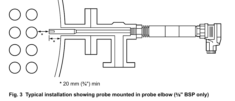
For selection, the CP30 technical information gives a nominal pressure rating of PN40, a maximum boiler pressure of 32 bar g and a maximum operating temperature of 239°C. The maximum ambient temperature is 70°C. The specified minimum conductivity is 10 µS/cm or 10 ppm. The maximum cable length between probe and controller is 100 m, subject to the controller instructions and the applicable wiring requirements.
| Selection item | CP30 information |
|---|---|
| Nominal electrode lengths | 300, 500, 1000 and 1500 mm |
| Standard connection | 3/8 inch BSP taper with DIN 43650 socket and Pg11 gland |
| UL connection option | 1/2 inch NPT conduit thread adaptor with four flying leads |
| Nominal pressure rating | PN40 |
| Maximum boiler pressure / temperature | 32 bar g / 239°C |
| Minimum vertical immersion | 100 mm |
| Minimum tip distance from boiler tubes | 20 mm |
| Maximum probe-to-controller cable length | 100 m |
These limits are not a substitute for checking the complete boiler system. Pressure, temperature, materials, electrical compatibility, local regulations and the controller’s own operating limits all need to be considered together. Where a local or regional version has a different connection or approval basis, the applicable CP30 technical sheet and installation instructions take precedence over a general description.
The standard cable socket is supplied with a gasket between the socket and the probe connector. It must remain in place when the socket is reconnected so that the environmental integrity of the connection is maintained. The installation instructions call for high-temperature screened cable and limit the probe-to-controller run to 100 m. The standard connector block can be rotated in 90-degree steps to assist wiring; the UL version uses its flying leads and conduit arrangement and should not be rotated in the same way.
Frequent probe maintenance should not normally be necessary, but scaling is an important diagnostic signal. If scale is found on the electrode, the boiler water treatment should be reviewed without delay. The installation instructions describe cleaning, inspection and continuity checks, and identify a replacement probe tip and spring assembly. Those procedures should be carried out by competent personnel with the boiler isolated, depressurised and safe to access.
When these points are confirmed, specify the Spirax Sarco CP30 conductivity probe with the required nominal electrode length and connection version. The resulting selection keeps the probe, controller and boiler installation aligned, while leaving the final electrode length to be matched accurately to the actual insertion depth.
The Spirax Sarco CP30 is a cut-to-length conductivity probe for steam boiler TDS monitoring and blowdown control systems. It combines austenitic stainless steel and PTFE wetted materials with four nominal probe lengths, standard or UL connection options, and a defined operating envelope up to 32 bar g and 239°C. For a reliable selection, treat CP30 as one part of the complete boiler water control arrangement and confirm the controller, connection standard, insertion geometry, electrical route and water-treatment conditions together.
English rendering of the selected CP30 technical information sheet TI-P403-49 AB Issue 4. The scope is the CP30 probe only; the original sheet is Chinese.
The Spirax Sarco CP30 conductivity probe is connected to a controller to measure the conductivity, or total dissolved solids (TDS), of water. It is normally used for monitoring and controlling blowdown on steam boilers. The probe may be installed in a Spirax Sarco probe elbow, through a screwed flange or directly in a boiler connection. The electrode is supplied in four nominal lengths and is cut to the required length before installation.
| Item | CP30 information |
|---|---|
| Pressure rating | PN40 |
| Maximum boiler pressure | 32 bar g (464 psi g) |
| Maximum temperature | 239°C (462°F) |
| Maximum ambient temperature | 70°C (158°F) |
| Design maximum cold test pressure | 60 bar g (870 psi) |
| Minimum tip distance from boiler tubes | 20 mm (3/4 inch) |
| Minimum immersion depth for vertical installation | 100 mm (4 inches) |
| Maximum probe-to-controller cable length | 100 m (330 ft) |
| Minimum conductivity | 10 µS/cm or 10 ppm |
| Cable connection ingress protection | IP65 |
| Nominal length | Imperial equivalent |
|---|---|
| 300 mm | 11.8 inches |
| 500 mm | 19.7 inches |
| 1000 mm | 39.4 inches |
| 1500 mm | 59.0 inches |
| Part | Material |
|---|---|
| Cable plug | Polyamide |
| Flat gasket | Silicone rubber |
| Probe connector | Polyamide |
| Cover | Austenitic stainless steel |
| Nameplate | Polycarbonate |
| Probe body | Austenitic stainless steel, Type 316Ti, W/S No. 1.4571 |
| Probe electrode | Austenitic stainless steel, ASTM A276 316L |
| Probe sleeve | PTFE |
| Probe shroud | PTFE |
| Spring | Austenitic stainless steel, BS 2056 316 S42 |
| Dimension or weight item | Value |
|---|---|
| Cable connector removal distance | 15 mm (0.6 inch) |
| Connector/body dimension shown on the drawing | 39 mm (1.5 inches) |
| Probe body dimension shown on the drawing | 178 mm (7.0 inches) |
| Probe body diameter | 28 mm (1.1 inches) |
| Spanner size across flats | 27 mm |
| Probe electrode diameter | 6 mm (0.24 inch) |
| Probe tip diameter | 11 mm (0.43 inch) |
| Approximate weight, 300 / 500 / 1000 / 1500 mm | 0.47 / 0.49 / 0.59 / 0.68 kg (1.0 / 1.1 / 1.3 / 1.5 lb) |
Probes up to and including 500 mm may be installed vertically or horizontally. Longer probes must be installed vertically. Position the probe so it senses representative boiler water and, where possible, keep it away from the feedwater inlet. The probe is used with a 3/8 inch BSP or 1/2 inch NPT female thread connection as applicable to the selected version.
Ordering example: one CP30 with a 500 mm probe and 3/8 inch BSP thread. The listed spare is a probe shroud and spring assembly. The separate installation and maintenance instructions below contain the cutting, wiring, removal, cleaning and inspection procedures.
The technical sheet states that the UL version has a 1/2 inch NPT connection, is approved to UL61010 and is not CE marked. Confirm the applicable regional approval and connection standard for the installation.
English installation and maintenance content selected from IM-P403-34 AB Issue 10, covering the CP30 conductivity probe. Installation, commissioning, wiring and maintenance must be carried out by qualified or suitably competent personnel in accordance with the complete manufacturer instructions and local requirements.
Use the CP30 only after checking the installation and maintenance instructions, nameplate and technical information sheet. The product is intended for steam and water service; consult Spirax Sarco before considering other fluids. Check material suitability, pressure, temperature and their maximum and minimum values against the complete system, and provide safety devices where a product limit could otherwise be exceeded.
Do not install the probe outdoors without additional weather protection. Keep drain and vent holes clear. Before installation or removal, isolate pressure and safely vent to atmosphere; do not assume the system is depressurised because a gauge reads zero. Allow hot parts to cool and take account of hot surfaces, hazardous fluids, explosion risks, confined or oxygen-deficient spaces, moving machinery, falling objects and other site hazards.
Before installation, consult the boiler manufacturer where possible for the probe position and optimum TDS level. Probes up to and including 500 mm may be installed vertically or horizontally; longer probes must be installed vertically. Install the probe where it can sense boiler-water conductivity, away from the feedwater inlet if possible. Keep the probe tip at least 20 mm from boiler tubes and immerse a vertically installed probe by at least 100 mm.
The boiler must be depressurised and vented to atmosphere before the probe is installed. Remove the label from the probe tip before installation.
The PTFE probe tip is retained on the electrode by an internal spring and turns freely in one direction only, which depends on how the spring is fitted. Do not force the tip or remove it without turning it at the same time, and do not attempt to remove the spring from the tip.
For subsequent removal or refitting, first ensure the boiler or vessel is depressurised and vented. Use the correct size spanner, inspect both threads for damage caused by overtightening or galling, replace a damaged probe, and keep drain and vent holes clear.
Install cabling to BS 6739 or a local equivalent. In the United States and Canada, wire the probe to the National and Local Electrical Code (NEC) or Canadian Electrical Code (CEC). For the standard CP30, use 2- or 4-core, 1 mm² (18–16 AWG), high-temperature screened cable. The maximum probe-to-controller cable length is 100 m (330 ft). Provide enough cable to remove the socket without placing strain on the probe.
The probe is supplied with a gasket between the cable socket and probe connector. Keep the gasket in place whenever the socket is reconnected; contact surfaces must be clean and undamaged. The standard connector block can be rotated in 90-degree steps to assist wiring. The UL version cannot be rotated in this way.
For the UL version, use Class 1 screened cable with a minimum suitable temperature rating of 75°C (167°F) between the terminal box and controller. The supplied four 18 AWG flying leads are 300 mm (12 inches) long and rated to 105°C (221°F); do not exceed that rating. Use a length of flexible metal conduit between the probe and a suitable metal terminal box. Do not place other control wiring in the conduit or terminal box, and prevent condensation from accumulating in the probe connector or terminal box.
Frequent maintenance should not normally be necessary. Clean the probe body with a cloth dampened with tap water, de-ionised water or isopropyl alcohol; other cleaning materials may damage the product and invalidate the warranty. Remove the probe once a year, remove the probe tip, clean the electrode end with fine emery cloth, clean the PTFE tip and sleeving with a cloth or bristle brush, and ensure that the tip is flush with the electrode before refitting it.
Scale on the electrode indicates that scale may also be forming elsewhere in the boiler. Obtain boiler-water-treatment advice without delay. A probe-conditioning option on some controllers may minimise the effect of scaling, but it is not a substitute for adequate boiler-water treatment.
Many installation faults can be traced to incorrect wiring. Check the wiring and controller links. A Spirax Sarco MS1 conductivity meter and extension lead can be used to check the AC resistance of an installed probe. For a continuity check, test from the probe tip to plug terminals 1 and 2, and from the probe body to plug terminal 3 and earth.
The spare probe tip and spring assembly is part number 4031280. Clean and chamfer the electrode before fitting the replacement assembly; wind the tip and spring onto the electrode until the probe rod is level with the end of the tip shroud. A small amount of free play is normal.
| Document | Reference | Language | Download |
|---|---|---|---|
| CP30 Conductivity Probe | IM-P403-34-US | English | Download |
CP30 selection is normally confirmed with the controller, mounting position, probe length, thread standard and boiler water TDS control target.
Return to the wider TDS blowdown controls route when the project is still comparing controllers, probes and blowdown valve arrangements.
If the system needs automatic TDS blowdown control, continue by comparing BC3150 and BC3250 controllers.
If the system needs automatic TDS blowdown control, continue by comparing BC3150 and BC3250 controllers.