
Back to the TDS blowdown control family
Return to the wider TDS blowdown controls route when the project is still comparing measurement, probes and blowdown valve arrangements.
Boiler controls and systems > TDS blowdown controls
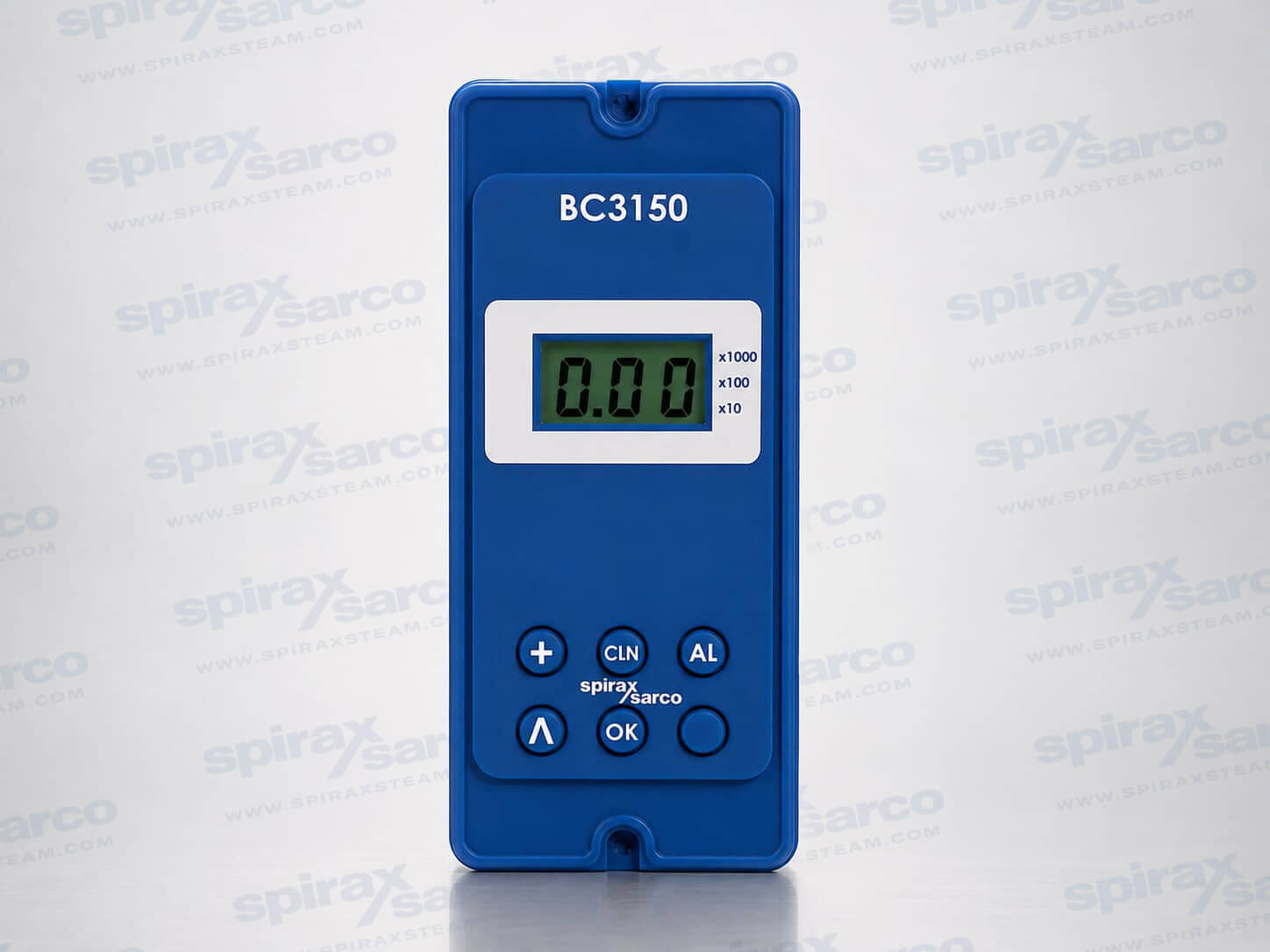
BC3150 Boiler Blowdown Controller
The BC3150 is a Spirax Sarco boiler blowdown controller that holds steam boiler water TDS on target by driving a blowdown valve from a conductivity probe signal. It works with CP10 and CP30 conductivity probes, accepts a Pt100 for temperature compensation, and offers continuous, purge or pulsed blowdown with a 4-20 mA retransmission output.
Quick facts
The Spirax Sarco BC3150 is a boiler blowdown controller for steam boilers. It continuously reads the conductivity of the boiler water, compares that reading with the total dissolved solids (TDS) level the plant has chosen, and opens and closes a blowdown valve to hold dissolved solids inside that band. It is a continuous-blowdown controller rather than a bottom-blowdown timer: it decides how much water leaves the boiler to keep the dissolved-solids concentration on target, and it does so without an operator standing at a valve. The Spirax Sarco BC3150 is the model to specify when a boiler house wants that automatic TDS control without also paying for bottom-blowdown timing, trending or Modbus communications in the same instrument.
The controller works with a Spirax Sarco conductivity probe and a boiler blowdown valve or condensate dump valve. Those three elements make the loop complete: the probe measures, the BC3150 decides, and the valve acts. Because the BC3150 is a panel-mounted instrument rather than a packaged skid, it is normally selected together with the probe, the valve and the sampling arrangement, and the values that matter most at commissioning are the TDS set point, the alarm level and the calibration figure.
Dissolved solids concentrate in a boiler as steam leaves and feedwater replaces it. Blowing down a proportion of the boiler water removes those solids, but blowing down more than necessary wastes treated water, heat and chemicals. The BC3150 automates that trade-off. A conductivity probe senses the water, the controller compares the reading against the set point, and the blowdown relay drives the valve.
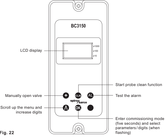
Once the controller is fully commissioned, the display alternates between the measured TDS value and a short status word: bLd while the blowdown relay is holding the valve open, AL while the alarm level has been exceeded, and Pur during a purge. The valve closes again once the reading has fallen clear of the threshold, by 5% of full scale at the set point and by 3% of full scale at the alarm. Those two fixed hysteresis bands are what stop the valve chattering around a single value.
Conductivity is displayed in microsiemens per centimetre or in parts per million, with microsiemens per centimetre as the default and a µS/cm to ppm conversion factor of 0.7. The working range is selected with a multiplier: 0 to 9.99 with no multiplier, 0 to 99.9 on x10, 0 to 999 on x100 and 0 to 9990 on x1000. Readings below 10% of the selected range are not accurate, which is why the range has to be matched to the boiler rather than left at its widest setting. If the controller is used only to raise an alarm, the set point can be pushed to 99.9% of full scale; if the alarm is not used at all, the alarm level is set to the same figure. Most commissioning parameters are protected by a pass code so that a casual button press cannot change how the boiler blows down, and the instrument has no battery: settings are held in non-volatile flash memory.
The BC3150 supports three ways of driving the blowdown valve, and the choice follows from where the probe is mounted and how large the boiler is.
Continuous output is used when the probe is mounted in the boiler itself. The probe then monitors the conductivity from the probe tip to the boiler shell the whole time, and the valve stays open until the conductivity falls below the set point hysteresis. This is the simplest arrangement and the one that gives the fastest response.
Purge output is used when the probe is mounted in the blowdown line instead. A probe in the blowdown line only sees a representative boiler sample while the valve is open, so the controller opens the valve for an adjustable purge period, takes the reading at boiler temperature, and then decides. Purge duration is adjustable from 0 to 99 seconds, and a purge occurs every 30 minutes, either independently of burner firing or based on cumulative boiler firing time. Purge time is set to zero when the probe is installed in the boiler.
Pulsed output suits smaller boilers where the blowdown valve capacity is high relative to the boiler size. Rather than holding the valve open, the controller opens it for 10 seconds and closes it for 20 seconds until the conductivity falls below the set point plus hysteresis. Pulsing slows the rate at which boiler water is removed so that the water level is not unduly disturbed, which avoids the risk of triggering a low water alarm. Pulsed output is suitable for solenoid or pneumatic valves only and must not be used with motorised valves. When the probe is in the boiler and no purge is set, a filter can be switched in to damp the probe output: 64 seconds when on, or 8 seconds when off.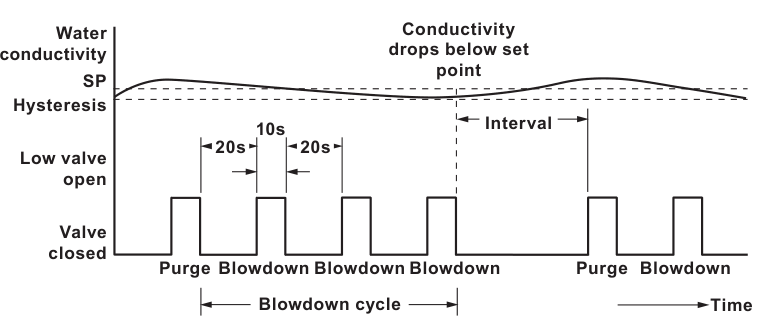
The BC3150 accepts a signal from a Spirax Sarco conductivity probe. The CP30 conductivity probe and the CP10 probe both give the controller its scale monitoring and self-cleaning features. A CP32 probe can also be used with the BC3150, but it does not provide scale monitoring or self-cleaning, so the choice of probe changes what the instrument can report about its own sensor. Probe cleaning is driven from the keypad: pressing CLN electrically cleans the probe for 20 seconds, after which the controller waits a further 20 seconds before returning to normal control so that any bubbles disperse.
A Pt100 temperature sensor can be connected to provide temperature compensation at 2% per °C, and this is recommended when the boiler works at varying pressures or in applications such as condensate monitoring or coil boilers where the water temperature varies. If no Pt100 is fitted, the controller falls back to a default water temperature of 184 °C, which corresponds to 10 bar g; the compensation range is 0 to 250 °C, and when no Pt100 is present the user enters an estimated average temperature between 100 and 250 °C in 1 °C steps. Conductivity accuracy is ±2.5% of full scale, possibly better in high EMC locations, with the narrowest 0 to 9.99 range quoted at ±5%. Probe cabling has to respect length limits that follow the range in use: cable runs are limited to 100 m on the two widest ranges, 30 m on the 99.90 range and 10 m on the narrowest 9.990 range, all in the same gauge, with a resistance from the probe body to the pipework or boiler shell of less than 1 ohm.
Spirax Sarco documents four standard boiler control system layouts, BCS1 to BCS4, which differ in where the probe and the valve sit relative to the boiler and its blowdown line. The BCS1 layout shown here is the classic continuous-blowdown arrangement: a probe and blowdown valve assembly on the boiler, wired back to a BC3150 mounted in the control panel.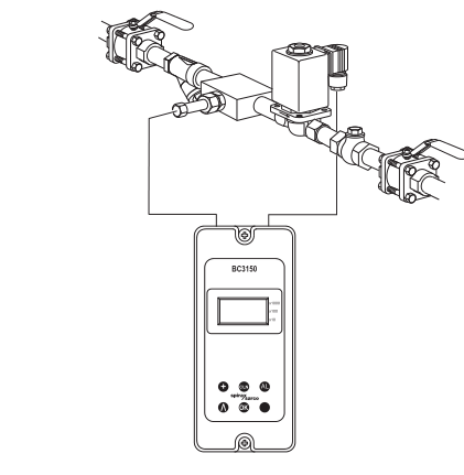
The same controller can be applied to a condensate contamination detection system, where it monitors and displays the conductivity of condensate returning to the feedtank and diverts the flow to drain when the conductivity rises above a preset level, so that contaminated water is not returned to the boiler. It is worth being clear about the limit of that method: it will not detect contaminants that do not change conductivity, such as oils, fats or sugars.
A typical installation mounts a conductivity sensor and a temperature sensor in a bypass line, with a check valve in the main line to ensure flow past the sensor under low-flow conditions and a 500 mm head to prevent flash steam entering the bypass. A three-port diverter valve with a spring-retract pneumatic actuator is the usual choice, arranged so that the valve diverts if the air supply fails; two two-port valves can be used instead, with a spring-to-close isolating valve on the condensate return and a spring-to-open dump valve on the drain. Most countries limit the temperature and contamination level of fluid dumped to drain, so the site's own regulations and the guidance issued by bodies such as the UK Health and Safety Executive apply.
An isolated 4 to 20 mA output is provided as standard. It retransmits the measured conductivity or TDS against the full-scale range and can drive a remote TDS display or feed a computerised management system. The output can be set to 0 to 20 mA or 4 to 20 mA, it will drive up to 500 ohm, and it is isolated to 100 V. Where a purge time has been set, the output holds the value recorded at the end of the last purge cycle rather than following the probe while the valve is closed.
Two single-pole changeover relays are fitted, one for the blowdown valve and one for the alarm, rated at 250 Vac with a resistive load of 3 A, an inductive load of 1 A, an ac motor load of ¼ HP at 250 Vac and a pilot duty rating of C300. Products in the range can communicate over an infrared link between adjacent controllers, which allows the parameters of this instrument to be passed to a controller fitted with RS485. The BC3150 is always the infrared slave, but the infrared beam between products must not be covered or obstructed.
The controller must be installed inside a suitable industrial control panel or fireproof enclosure, to at least IP54 or UL50/NEMA type 3, 3S, 4, 4X, 6, 6P or 13, so that it is protected from impact and from its surroundings; a harsh environment with conductive dust or wet conditions needs additional protection, and the instrument must not be mounted outdoors without extra weather protection. It must be installed vertically, with the display readable by the operator, and a minimum gap of 15 mm is needed between units for cooling. The enclosure is sealed and has no replaceable parts or internal switches, so it must not be opened.
For panel mounting, the front panel carries M4 × 0.7 threaded inserts top and bottom, and the cutout measures 45 mm by 92 mm, with 4.2 mm fixing holes on 67 mm centres set 10 mm inside the top and bottom edges of the bezel outline. The supplied M4 × 25 mm screws must be used, tightened to 1.0 to 1.2 Nm; longer screws carry a risk of electric shock. For DIN rail mounting a clip and self-tapping screws fix the unit to a 35 mm rail, and for chassis plate mounting the unit is secured through the slots at the top and bottom of the case. The case must never be drilled. The installation also has to provide the overcurrent protection and primary isolation the instrument relies on, and a disconnecting device that breaks all phase conductors must be fitted within easy reach of the operator and marked as the disconnecting device for this product.
Before a Spirax Sarco BC3150 is ordered, four things are worth confirming. First, where the probe will be mounted, because a probe in the boiler uses continuous output while a probe in the blowdown line needs a purge time and a burner input. Second, which probe is being used, since CP10 and CP30 bring scale monitoring and self-cleaning that a CP32 does not. Third, whether the water temperature varies enough to justify a Pt100, and if not, what average temperature should be entered in place of the 184 °C default. Fourth, what the boiler manufacturer specifies as the TDS set point and alarm level, because those two figures drive the whole loop and the calibration that follows.
Calibration is the setting that most affects performance. The boiler must be at working temperature when the system is calibrated, which is particularly important when no temperature sensor is fitted, and both the set point and the calibration figure must be greater than 10% of the chosen range. Accuracy is best when the controller is calibrated with the TDS as close as possible to the set point, and the calibration should be rechecked once the boiler has settled and then checked weekly.
If the requirement grows beyond TDS control, the BC3250 boiler blowdown controller adds bottom blowdown timing, trend display and Modbus communications in the same instrument. A blowdown valve package, the bottom blowdown system for the manual or timed sludge blowdown that continuous TDS control does not replace, and the wider TDS blowdown controls range are the other parts of the selection. The measurement side of the project is covered by conductivity meters, and the background to the control problem is set out in controlling TDS in the boiler water, water treatment, storage and blowdown for steam boilers and bottom blowdown. The full range sits under boiler controls and systems.
The BC3150 is ordered as a single instrument, for example one Spirax Sarco BC3150 blowdown controller, and the conductivity probe, blowdown valve and mounting accessories are ordered separately against the same selection. Confirm the probe type, the probe mounting position, the valve package, the panel space and the required output signal with your local Spirax Sarco representative before the order is placed.
This fragment preserves the published technical information for the BC3150 boiler blowdown controller. The description, features, certification basis, input and output data, cable data, dimensions, weight, product description and ordering information are taken from the BC3150 technical information sheet TI-P403-91, AB Issue 6. That sheet is published in Chinese only; no English edition exists on any Spirax Sarco market. Where the current installation and maintenance instructions IM-P403-88, EMM Issue 7, restate the same technical data in English, the English wording and the newer values have been followed, and the differences are noted in the relevant table. Local regulations may restrict the use of this product to below the conditions quoted, and in the interests of development and improvement Spirax Sarco reserves the right to change the specification without notice.
The BC3150 is a blowdown controller for steam boilers. It controls TDS (total dissolved solids, the salts in solution) by opening and closing a blowdown valve. The product works by controlling the conductivity of liquids, in conjunction with a Spirax Sarco conductivity sensor and a boiler blowdown valve or condensate dump valve.
The product is available for panel, DIN rail or chassis plate mounting and is supplied from a 110 V to 240 Vac supply. The front panel has a three-digit LCD display and a five-button keypad. The product has no battery; the parameter settings are held in non-volatile memory (Flash) and are written after a parameter is changed and the OK button is pressed.
The BC3150 complies with the Electromagnetic Compatibility Directive 2014/30/EU and all its requirements. The product is suitable for Class A environments (for example industrial). A fully detailed EMC assessment has been made under the reference number UK Supply BH BC3150 2008.
The BC3150 complies with the Low Voltage Directive. It meets the standards of EN 61010-1, Safety requirements for electrical equipment for measurement, control and laboratory use; UL 61010-1, 3rd Edition, 2012-05; and CAN/CSA-C22.2 No. 61010-1, 3rd Edition, 2012-05. The technical information sheet quotes EN 61010-1:2001 for the same requirement; the current installation and maintenance instructions quote EN 61010-1:2010, and the later edition is the one to read.
The product has been type tested as a TDS controller to Vd TÜV Wasser 100 (07:2006). The BC3150 is UL listed (open).
All ranges and operating parameters are selected through the software menu. Commissioning is carried out using the buttons on the front panel. Once the controller is fully commissioned, the TDS value is displayed in µS/cm, with ppm available as an option.
If the conductivity exceeds the set point, the display alternates between the TDS value and bLd, and the valve relay is energised until the conductivity falls to 5% of full scale below the set point. If the conductivity exceeds the alarm value, the display alternates between the TDS value and AL, and the valve relay is energised until the conductivity falls to 3% of full scale below the alarm point. If the system is carrying out a purge, the display alternates between the TDS value and Pur, and the valve relay is energised until the conductivity falls to 5% of full scale below the set point.
The BC3150 accepts a signal from a Spirax Sarco conductivity sensor (CP10, CP30 or CP32). A Pt100 temperature sensor can be connected to the controller to provide temperature compensation at 2% per °C. Temperature compensation is recommended if the boiler is working at varying pressures, or in other applications such as condensate recovery or coil boilers where the temperature varies. If a Pt100 is not fitted, the default temperature setting is 184 °C (10 bar g).
Pulse output. For small boilers where the capacity of the blowdown valve is relatively high compared with the boiler capacity, pulsed blowdown may be used instead of continuous blowdown: the valve opens for 10 seconds and then closes for 20 seconds. This slows the rate at which the boiler water is discharged, prevents the boiler water level from being affected, and avoids the risk of triggering a low water alarm.
4 to 20 mA output. A standard 4 to 20 mA output is provided, which may be used for remote TDS display or as an input signal to a computerised management system.
To prevent unwanted or inadvertent settings being made, all commissioning parameters are protected with a pass code.
The product can communicate with adjacent boiler controllers (Spirax Sarco products only) by infrared. Within range, adjacent products can communicate over the infrared bus. This allows the parameters of the product (OEM) to be transmitted to a device fitted with RS485 (USER). The product can only be configured as an IR slave; no setting or adjustment is required.
| Mains voltage range | 110 V to 240 Vac at 50/60 Hz |
|---|---|
| Power consumption | 7.5 W (maximum) |
| General | Indoor use only |
| Maximum altitude | 2 000 m (6 562 ft) above sea level |
| Ambient temperature range | 0 to 55 °C (32 to 131 °F) |
| Maximum relative humidity | 80% up to 31 °C (88 °F), decreasing linearly to 50% at 40 °C (104 °F) |
| Overvoltage category | III |
| Pollution degree | 2 (as supplied); 3 when installed in an enclosure, with a minimum of IP54 or UL50/NEMA Type 3, 3S, 4, 4X, 6, 6P or 13 |
| Enclosure rating (front panel only) | NEMA Type 4 hose down only (UL approval) and IP65 (verified by TRAC Global) |
| Torque rating for panel screws | 1 to 1.2 Nm |
| LVD (safety) | Electrical safety EN 61010-1; UL 61010-1, 3rd Edition, 2012-05; CAN/CSA-C22.2 No. 61010-1, 3rd Edition, 2012-05 |
| EMC immunity and emissions | Suitable for heavy industrial locations |
| Enclosure material | Polycarbonate |
| Front panel material | Silicone rubber, 60 shore |
| Solder | Tin/lead (60/40%) |
| Mains and signal connector termination | Rising clamp plug-in terminal blocks with screwed connectors |
|---|---|
| Cable size | 0.2 mm² (24 AWG) to 2.5 mm². The technical information sheet quotes the upper limit as 12 AWG and the installation and maintenance instructions as 14 AWG for the same 2.5 mm²; use the metric figure. |
| Stripping length | 5 to 6 mm |
| Connector note | Use only the connectors supplied by Spirax-Sarco Limited, otherwise safety and approvals may be compromised |
| TDS probe cable type | High temperature, screened, 4 cores (CP10 and CP20; for most applications the 1.25 m (4 ft) heat resistant cable will need to be extended using a junction box) |
| TDS probe cable gauge | 1 to 1.5 mm² (18 to 16 AWG) |
| TDS probe cable maximum length | 100 m on the 9990 and 999.0 ranges; 30 m on the 99.90 range; 10 m on the 9.990 range |
| TDS probe cable recommended type | Prysmian (Pirelli) FP200, Delta Crompton Firetuf OHLS |
| Pt100 probe cable type | High temperature, twisted, screened, 3 cores |
| Pt100 probe cable gauge | 1 to 1.5 mm² (18 to 16 AWG) |
| Pt100 probe cable maximum length | 100 m (328 ft) |
| 4 to 20 mA output cable type | Twisted pair, screened, 1 pair |
| 4 to 20 mA output cable gauge | 0.23 to 1 mm² (24 to 18 AWG) |
| 4 to 20 mA output cable maximum length | 100 m |
| Water conductivity probe types | CP10, CP30 and CP32 |
|---|---|
| Water conductivity ranges | 0 to 9.99, 0 to 99.9, 0 to 999 and 0 to 9990 ppm or µS/cm; minimum ≥ 1 µS at 25 °C |
| Water conductivity accuracy | ±2.5% FSD (possibly better in high EMC locations); ±5% FSD on the 0 to 9.999 range |
| µS/cm to ppm conversion factor | 0.7 |
| Neutralising factor | 0.7 |
| Water conductivity resolution | 0.1% FSD |
| Water conductivity drive | ac, 4 wires |
| Temperature compensation sensor type | Pt100, Class B or better |
| Temperature compensation range | 0 to 250 °C. With no Pt100 fitted, the user programs a temperature of 100 to 250 °C in 1 °C steps |
| Temperature compensation accuracy | ±2.5% FSD; system accuracy ±5% |
| Temperature compensation resolution | 0.1% FSD (1% FSD in the installation and maintenance instructions) |
| Temperature compensation drive | dc, 3 wires |
| Probe cleaning maximum voltage | 32 Vdc |
|---|---|
| Probe cleaning drive | Pulsed, 1 second on and 1 second off |
| Probe cleaning time | 20 seconds |
| 4 to 20 mA minimum current | 0 mA |
| 4 to 20 mA maximum current | 20 mA |
| 4 to 20 mA open circuit voltage (maximum) | 19 Vdc |
| 4 to 20 mA resolution | 0.1% FSD |
| 4 to 20 mA maximum output load | 500 ohm |
| 4 to 20 mA isolation | 100 V |
| 4 to 20 mA output rate | 10 per second |
| Relay contacts | 2 × single pole changeover relays (SPCO) |
| Relay voltage rating (maximum) | 250 Vac |
| Relay resistive load | 3 A at 250 Vac |
| Relay inductive load | 1 A at 250 Vac |
| Relay ac motor load | ¼ HP (2.9 A) at 250 Vac; 1/10 HP (3 A) at 120 Vac |
| Relay pilot duty load | C300 (2.5 A), control circuit and coils |
| Relay electrical life | 3 × 10⁵ operations or greater, depending on load |
| Relay mechanical life | 30 × 10⁶ operations |
The panel cutout is 45 mm by 92 mm with 4.2 mm diameter fixing holes at 67 mm centres, set 10 mm in from the top and bottom of the bezel outline, which is 112 mm high. A minimum gap of 15 mm must be provided between units for product cooling, and the mounting hole dimensions are the same for both panel and wall mounting. The approximate weight of the product is 475 g.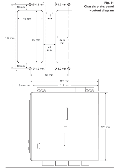
The product is a blowdown controller with an LCD display, a five-button keypad and infrared communication.
How to order, for example: 1 off Spirax Sarco BC3150 blowdown controller.
Warning: this document does not contain sufficient information for the safe installation of the product. The product operates at hazardous voltages, and the installation and maintenance instructions supplied with the product must be consulted before the product is installed.
Caution: before installing the product and connecting the power supply, ensure that there is no condensation inside the product. The product may be mounted on a DIN rail, a chassis plate or a panel, and a bezel is supplied.
The product must be installed in a suitable industrial control panel or fireproof enclosure to provide impact and environmental protection. A minimum of IP54 (EN 60529) or Type 3, 3S, 4, 4X, 6, 6P and 13 (UL50/NEMA 250) is required. Spirax Sarco supplies suitable plastic and metal enclosures.
In the United Kingdom, IEE Regulations (BS 7671) must be followed; elsewhere, the corresponding local regulations apply. All wiring materials and methods must comply with the relevant EN and IEC standards. No special servicing, preventive maintenance or product inspection is required. Boiler water level controls and alarms do require testing and inspection, and Health and Safety Executive guidance note PM5 gives general guidance.
This fragment preserves the published installation and maintenance instructions for the BC3150 Blowdown Controller, document IM-P403-88, EMM Issue 7, part number 4033352/7. The safety information, user instructions, system overview, mechanical and electrical installation, commissioning, communications, maintenance and fault finding sections are reproduced for the BC3150. The generic technical tables in Section 10 of the original manual repeat the BC3150 technical information sheet and are therefore not duplicated here; the programming parameters and default settings, which appear only in the manual, are retained, as are the data register appendix and the menu map. Section headings and numbering follow the original document so that the manual can be used alongside this page. Safe operation of this product can only be guaranteed if it is properly installed, commissioned, used and maintained by qualified personnel in compliance with these instructions.
Safe operation of this product can only be guaranteed if it is properly installed, commissioned, used and maintained by qualified personnel (see Section 1.11) in compliance with the operating instructions. General installation and safety instructions for pipeline and plant construction, as well as the proper use of tools and safety equipment, must also be complied with. Your attention is drawn to IEE Regulations (BS 7671, EN 12953, EN 12952 and EN 50156). Elsewhere, other regulations will normally apply. All wiring materials and methods shall comply with relevant EN and IEC standards where applicable.
Warning: this product is designed and constructed to withstand the forces encountered during normal use. Use of the product other than as a boiler controller, or failure to install the product in accordance with these instructions, product modifications or repair could cause injury or fatality to personnel, cause damage to the product or property, or invalidate the marking. These instructions must be stored in a safe place near the installation of the product at all times.
Warning: this product complies with Electromagnetic Compatibility Directive 2014/30/EU and all its requirements. It is suitable for Class A environments (for example industrial). A fully detailed EMC assessment has been made and has the reference number UK Supply BH BC3150 2008. The product may be exposed to interference above the limits of Heavy Industrial Immunity if the product or its wiring is located near a radio transmitter; if excessive electrical noise occurs on the mains supply, ac power line protectors should be installed, and these can combine filtering, suppression, surge and spike arrestors; cellular telephones and mobile radios may cause interference if used within approximately 1 metre (39 inches) of the product or its wiring, and the actual separation distance necessary will vary according to the surroundings of the installation and the power of the transmitter.
The product complies with Low Voltage Directive 2014/35/EU by meeting the standards of EN 61010-1:2010, Safety requirements for electrical equipment for measurement, control and laboratory use.
Ensure safe access and if necessary a safe working platform (suitably guarded) before attempting to work on the product. Arrange suitable lifting gear if required.
Ensure adequate lighting, particularly where detailed or intricate work is required.
Consider what is in the pipeline or what may have been in the pipeline at some previous time. Consider flammable materials, substances hazardous to health, and extremes of temperature.
Consider explosion risk areas, lack of oxygen (for example tanks and pits), dangerous gases, extremes of temperature, hot surfaces, fire hazard (for example during welding), excessive noise and moving machinery.
Consider the effect on the complete system of the work proposed. Will any proposed action, such as closing isolation valves or electrical isolation, put any other part of the system or any personnel at risk? Dangers might include isolation of vents or protective devices, or the rendering ineffective of controls or alarms. Ensure isolation valves are turned on and off in a gradual way to avoid system shocks.
Ensure that any pressure is isolated and safely vented to atmospheric pressure. Consider double isolation (double block and bleed) and the locking or labelling of closed valves. Do not assume that the system has depressurised even when the pressure gauge indicates zero.
Allow time for temperature to normalise after isolation to avoid danger of burns.
Before starting work ensure that you have suitable tools and/or consumables available. Use only genuine Spirax Sarco replacement parts.
Consider whether you and/or others in the vicinity require any protective clothing to protect against the hazards of, for example, chemicals, high and low temperature, radiation, noise, falling objects, and dangers to eyes and face.
All work must be carried out or be supervised by a suitably competent person. Installation and operating personnel should be trained in the correct use of the product according to the Installation and Maintenance Instructions. Where a formal permit to work system is in force it must be complied with. Where there is no such system, it is recommended that a responsible person should know what work is going on and, where necessary, arrange to have an assistant whose primary responsibility is safety. Post warning notices if necessary.
Manual handling of large and/or heavy products may present a risk of injury. Lifting, pushing, pulling, carrying or supporting a load by bodily force can cause injury, particularly to the back. You are advised to assess the risks taking into account the task, the individual, the load and the working environment, and use the appropriate handling method depending on the circumstances of the work being done.
In normal use the external surface of the product may be very hot. Many products are not self-draining. Take due care when dismantling or removing the product from an installation.
Provision must be made to protect products that are not self-draining against frost damage in environments where they may be exposed to temperatures below freezing point.
On disposal of the unit or component, appropriate precautions should be taken in accordance with local and national regulations. Unless otherwise stated in the Installation and Maintenance Instructions, this product is recyclable and no ecological hazard is anticipated with its disposal providing due care is taken.
Customers and stockists are reminded that under EC Health, Safety and Environment Law, when returning products to Spirax Sarco they must provide information on any hazards and the precautions to be taken due to contamination residues or mechanical damage which may present a health, safety or environmental risk. This information must be provided in writing, including Health and Safety data sheets relating to any substances identified as hazardous or potentially hazardous.
Certain computer programs contained in this product were developed by Spirax-Sarco Limited. Copyright © Spirax-Sarco Limited 2017. All rights reserved. Spirax-Sarco Limited grants the legal user of this product the right to use the programs solely within the scope of the legitimate operation of the product. No other right is granted under this licence, and the programs may not be used, sold, licensed, transferred, copied or reproduced in whole or in part in any manner or form other than as expressly granted without the prior written consent of Spirax-Sarco Limited.
The BC3150 is a blowdown controller for steam boilers. It controls TDS (total dissolved solids, the salts in solution) by opening and closing a blowdown valve. The product works by controlling the conductivity of liquids, in conjunction with a Spirax Sarco conductivity sensor and a boiler blowdown valve or condensate dump valve.
The front panel has a three-digit LCD graphic display and a five-button keypad. The up-arrow button scrolls through the menus. The OK button enters the commissioning mode when pressed and held for five seconds, and when CAL is selected it allows the product to be calibrated from the run menu without entering the password protected commissioning menu. The AL button tests the alarm relay and the external circuits. The CLN button starts the probe clean function. The valve button manually opens the valve.
When these buttons are released, the product returns to the process variable or end display, depending on whether they were pressed in run or commissioning mode.
AL + tSt (test) + the process variable. The alarm only occurs while the key is pressed.Additional information on probe cleaning. If it is found that the calibration has drifted to more than twice its original setting, the probe may need cleaning. Fifteen minutes after the probe has been cleaned it should be possible to recalibrate the controller near to its original level. If not, the probe may not be sufficiently clean, so the cleaning procedure should be repeated. In most cases the controller can then be recalibrated. In exceptional circumstances, where abnormal scaling has been allowed to occur in the boiler, it may still not be possible to recalibrate the controller; in this case it is permissible to repeat the cleaning period in 5-minute steps up to a maximum of 30 minutes, checking the calibration after each step, and waiting 15 minutes after each cycle to allow the system to stabilise.
Important note: the use of the probe cleaning function must not be regarded as a substitute for adequate water treatment. If scale is forming on the probe tip it is a certain warning that scale will also be forming on the boiler tubes, and boiler water treatment must be investigated. Over-use of the probe cleaning function may shorten the life of the probe.
Pressing the up-arrow button in run mode steps through the parameters selected, and each parameter remains on view for a further 2 minutes unless the button is pressed again. After power is initially applied the product automatically enters run mode, and the current conductivity or TDS is displayed, or 000 if a purge time has been set or the product has not been calibrated. In normal operation the display shows the actual total dissolved solids value in µS/cm or ppm, depending on the option chosen, and once fully commissioned the TDS value alternates with information about alarms and the valve status.
The alarm indications show that the alarm relay has been de-energised or released, that the operator is testing the alarm relay, or that the process variable has exceeded the alarm level. The probe cleaning and conditioning indication shows that the operator has started a cleaning cycle. The TDS blowdown valve indications show that the blowdown relay is energised; that the TDS has increased above the set point and the blowdown valve is being pulsed open for 10 seconds on and 20 seconds off until the TDS drops below the hysteresis of the set point; that a purge period is in progress with the valve open, at the end of which the product will either indicate Hi or restart another purge interval; that the TDS has increased above the set point and the blowdown valve has been opened until the TDS drops below the hysteresis of the set point; or that the operator is testing the blowdown valve.
If an error occurs, an error menu ErX is displayed at the end of the parameter screens. Pressing and holding the OK button for 3 seconds clears a message and re-energises the alarm relays. If the cause has not been corrected the same error message reappears. If the error or alarm is of a latching type, only the message disappears; the alarm relay remains de-energised until the correct passcode is entered in the commissioning menu. If more than one error or alarm has occurred, the next message appears in priority order after the previous one has been cleared. See Section 9, Fault finding.
The product is tested, calibrated and inspected prior to shipment to ensure proper operation. Each carton should be inspected at the time of delivery for possible external damage, and any visible damage recorded immediately on the carrier's copy of the delivery slip. Each carton should be unpacked carefully and its contents checked for damage; if items are found to be damaged or missing, notify Spirax Sarco immediately and provide full details, and report the damage to the carrier with a request for their on-site inspection of the damaged item and its shipping carton.
If the product is to be stored for a period prior to installation, the environmental storage conditions should be at a temperature between 0 °C and 65 °C (32 °F and 149 °F), and between 10% and 90% relative humidity (non-condensing). Ensure there is no condensation within the unit before installing and connecting the power.
An alternative operator instruction manual, in place of this manual, for operating the equipment is required, so that the commissioning menu passcode is not disclosed to the operator. The alarm reset passcode may optionally be disclosed if this is deemed necessary.
The product can be configured to control the TDS or conductivity of water. Once fully commissioned, the TDS value is displayed in µS/cm, or ppm if selected. Conductivity is expressed in parts per million or micro Siemens per centimetre; micro Siemens per centimetre is becoming the more common unit and is therefore the default setting.
If the water conductivity exceeds the set point level, the TDS value shown on the display alternates with bLd, and the valve relay is energised until the conductivity drops to 5% of full scale below the set point. If the system is carrying out a purge, the TDS value alternates with Pur, and the valve relay is energised until the conductivity drops 5% of full scale below the set point. If the water conductivity exceeds the alarm level, the displayed TDS value alternates with AL, and the valve relay is energised until the conductivity drops 3% of full scale below the alarm level.
The product can accept a signal from a Spirax Sarco conductivity probe (CP10 or CP30) and a Pt100 temperature sensor. A CP32 probe may also be used with the BC3150, but will not provide the scale monitoring and self-cleaning features. A Pt100 temperature sensor may be connected to provide temperature compensation at 2% per °C. This is recommended if the boiler is working at varying pressures, or for other applications such as condensate monitoring or coil boilers where the temperature may vary. If a Pt100 is not fitted, the product uses a default temperature of 184 °C (10 bar g).
Continuous output. Used when the probe is mounted in the boiler. The probe is able to constantly monitor the conductivity from the probe tip to the boiler shell, and the valve is kept open until the conductivity drops below the set point hysteresis.
Purge output. Used only when the probe is mounted in the blowdown line. Purge ensures the sensor measures the conductivity at boiler temperature. The purge duration time is the time the valve is open to enable a representative boiler sample to reach the probe. A purge occurs every 30 minutes, either independent of burner firing or dependent on cumulative boiler firing time.
Pulsed output. For smaller boilers where the capacity of the blowdown valve is relatively high compared to the boiler size, the blowdown may be set to pulsed rather than continuous output, opening for 10 seconds and closing for 20 seconds. This slows the rate at which the boiler water is removed so that the level is not unduly affected, avoiding the risk of triggering a low water alarm.
4 to 20 mA retransmit. An isolated 4 to 20 mA output is provided as standard, and may be used for remote display of the TDS level or as an output to a computerised management system.
To prevent unwanted or inadvertent changes being made, most commissioning parameters are protected with a pass code. The BC3150 can communicate via an infrared link between adjacent controllers, as described in Section 7.
The controller is used in the four standard boiler control system arrangements, BCS1 to BCS4. BCS1 is the arrangement shown in the product introduction on this page, with the probe and blowdown valve assembly on the boiler and the controller in the control panel.
Most countries have regulations that limit temperature and contamination levels for fluids being dumped to drain, and it is also essential to follow guidelines issued by bodies such as the UK Health and Safety Executive. The Spirax Sarco condensate contamination detection system monitors and displays the conductivity of condensate return, and redirects the flow to drain if the conductivity increases above a pre-set level, to avoid contaminated water being returned to the boiler feedtank. It will not detect contaminants that do not change the conductivity, such as oils, fats or sugars.
A conductivity sensor and a temperature sensor are mounted in a bypass line. A check valve in the main line ensures a flow past the sensor under low flow conditions, and the 500 mm head prevents flash steam flow in the bypass line. A three-port diverter valve such as the Spirax Sarco QL is recommended, with a spring retract pneumatic actuator normally fitted to cause the valve to divert on failure of the air supply. Alternatively, two two-port valves such as the M20 may be used, one as a spring-to-close isolating valve in the condensate return line and one as a spring-to-open dump valve in the drain line; on detection of high conductivity the isolating valve closes and the dump valve opens, both under spring pressure. Suitable three-port solenoid valves may be selected from the Spirax Sarco range and are described in separate literature.
Read the Safety information in Section 1 before installing the product. The product must be installed in a suitable industrial control panel or fireproof enclosure to provide impact and environmental protection. A minimum of IP54 (EN 60529) or Type 3, 3S, 4, 4X, 6, 6P and 13 (UL50/NEMA 250) is required. If installed in a harsh environment with conductive dust and/or wet conditions, extra protection is required. During installation or maintenance the rear of the product must be protected from environmental pollutants entering the product, or the tasks can be performed in a dry clean environment.
Caution 1: the product must only be installed in the vertical orientation. Caution 2: do not cover or obstruct the infrared beam between products. Ensure that the display can be easily read by the operator. Warning: the boiler control panel or enclosure doors must be kept closed at all times unless installation or maintenance work is being carried out.
Install the product in an environment that minimises the effects of heat, vibration, shock and electrical interference. Do not install the product outdoors without additional weather protection. Do not attempt to open the product: it is sealed and has no replaceable parts or internal switches.
The product is provided with a clip and a set of self-tapping screws to secure it to a 35 mm DIN rail. On the rear of the enclosure, two sets of holes are provided to give two height positions, and the clip can be adjusted to give further positions. Locate the clip onto one set of holes and secure it using the two screws provided, then ensure the spring clip is fully engaged with the rail. Only use the screws provided with the product.
Drill holes in the chassis plate as shown in the cutout diagram, then fit the unit to the chassis plate and secure it with 2 screws, nuts and washers, using the slots provided at the top and bottom of the case. Do not drill the product case or use self-tapping screws.
The minimum panel thickness is 1 mm if the bezel is used. The product has integral threaded inserts (M4 × 0.7) at the top and bottom of the front panel, and two M4 × 25 mm screws are provided together with fibre washers and a bezel.
Fixing template notes: the solid line indicates the cutout required for panel mounting and the broken line indicates the product outline; a minimum gap of 15 mm between units must be provided for product cooling; and the mounting hole dimensions are the same for both panel and wall mounting.
Before installing, observe the Safety information in Section 1. Warning: isolate the mains supply before touching any of the wiring terminals, as these may be wired to hazardous voltages. Use only the connectors supplied with the product, or spares obtained from Spirax Sarco Ltd; use of different connectors may compromise product safety and approvals. Connecting the mains supply incorrectly can cause damage and may compromise safety.
Every effort has been made during the design of the product to ensure the safety of the user, but the following precautions must be observed.
The protective earth must be connected in accordance with national or local regulations. The relay terminals are numbered 1 to 11 and comprise the alarm 1 relay and the control relay, with a 1 A fuse on the alarm circuit and 3 A fuses on the control and burner circuits. Wiring arrangements are given in the manual for the BCV30 230/115 Vac blowdown valve, for BCV1, BCV20 or BCV31 solenoid valves, and for BCV4x, 6x, 7x and 8x blowdown valves on a 24 Vac/dc supply or a 100 to 110 Vac / 230 Vac supply, in both the two-cable three-point and the single-cable two-point arrangements, with or without the AVF234S limit switch box.
An earth current loop is created if a wire or screen is connected between two earth points that are at different potential. If the wiring diagram is followed correctly, the screen will only be connected to the earth at one end. The earth terminal is a functional earth rather than a protective earth. A protective earth provides protection from electric shock under a single fault condition; this product has double insulation and therefore does not require a protective earth. A functional earth is used in order for the product to operate: in this application the earth is used as a sink or drain for any electrical interference, and the earth terminal must be connected to a local earth in order to conform to the EMC directive.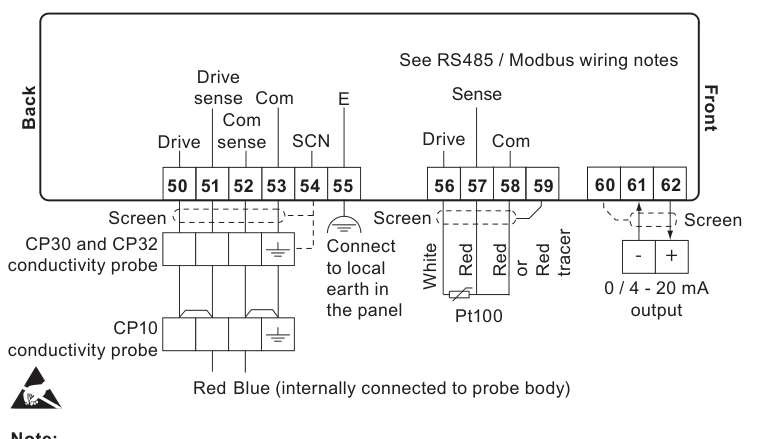
The maximum cable length for all probes is 100 m on the 9990 and 999.0 ranges, 10 m on the 9.990 range and 30 m on the 99.90 range. All cables must be of the same gauge. Do not connect terminals 53, 54, 59, 60 or 78 to any other earth, and ensure that the resistance from the probe body to the pipework or boiler shell is less than 1 ohm. The functional earth pins should be connected to earth local to the panel.
For most applications the 1.25 m (4 ft) heat resisting probe cable will need to be extended using a junction box. If it is not extended, link terminals 50 to 51 and 52 to 53. Whilst pairs of conductors are linked at the junction box, the four-wire connection is required to compensate for voltage drop.
The probe requires a 4 core screened cable connection. Whilst pairs of conductors are linked at the probe, the four-wire connection compensates for voltage drop along the cable. The CP30 UL recognized probe is supplied with four 18 AWG, 12 inch long colour coded flying leads; these are to be cut to length and wired to a suitable terminal block housed in a suitable metal box. A length of flexible metal conduit is required between the probe and the terminal box to provide environmental and impact protection and easy electrical connection, and the cable socket is provided with a ½ inch NPT conduit adaptor for this purpose. See the CP30 installation and maintenance instructions for further details.
A four wire Pt100 will have two wires of one colour and two wires of another colour. Link one of the pairs at the junction box and connect it to terminal 56, then connect one of the remaining two wires to terminal 57 and the other to terminal 58.
For the TP20, when the cable is to be longer than the 1.25 m (4 ft) supplied, a junction box and 3 core screened cable will be needed. Colour codes for sensor wires vary, but a three-wire sensor will normally have 2 wires of one colour and 1 wire of a different colour.
All commissioning for the product is carried out via the front panel. Warning: on entering the commissioning mode the product will cease normal control and the control relay will shut the valve. For safety, the alarm relay will continue to operate as normal. To regain normal control, return to the run menu by selecting end. If the purge time has been reset, a new purge interval will begin. If during commissioning the buttons are not pressed for over 5 minutes, the controller will revert to run mode and an error will be displayed; if the commissioning was incomplete the controller may not provide the correct control. The product has no battery: the programmed settings are held in non-volatile memory (Flash) and are written to after changing a parameter and pressing the OK button.
This section allows the user to carry out the minimum commissioning necessary to operate the system. It accepts the defaults set in the factory, so it will only work if the original default settings have not been altered. Settings can then be tailored to suit the individual requirements of the customer or application if required. This procedure assumes a Pt100 is fitted to the controller.
Warning: it is essential that you comply with national and local regulations and guidance notes, and the boiler manufacturer's recommendations. It is imperative that the settings you have accepted will allow the boiler to operate in a safe manner.
| Parameter | Action |
|---|---|
| Set Point | Set the TDS to the level at which the blowdown valve is to open and press the OK button. |
| Alarm | Set the TDS to the level at which the alarm is to operate and press the OK button. It must be higher than the set point. |
| Cal | Set the actual measured value of the TDS and press the OK button. |
Test the system to ensure that it is working correctly.
On entering the correct pass code, the display shows the main menu structure. The full commissioning menu covers the range multiplier, the conductivity units, the set point, the alarm, the alarm latch, the purge time, the burner input, the filter, calibration, pulsed output, the 4 to 20 mA output, internal temperature compensation and the probe factor, ending with End, which returns the product to run mode.
The range decimal point is used to select the most suitable range; follow the boiler manufacturer's recommendations. If the 0 to 9.99 range is required, do not select a multiplier; if the 0 to 99.9 range is required select x10; if the 0 to 999 range is required select x100; if the 0 to 9990 range is required select x1000. Press the OK button to accept the selection and move to the next menu option. Readings are not accurate below 10% of range.
Micro Siemens per centimetre is the preferred option. Press the OK button to select On for µS/cm, or the up-arrow button to select OFF for ppm, then press OK to confirm and move to the next menu option.
The set point is the TDS value at which the blowdown or dump valve will open. The boiler manufacturer should be consulted wherever possible to specify the most suitable value. It has a fixed hysteresis of 5%. If the controller is only being used to provide an alarm, set the set point reading to 99.9% of full scale. To select a set point, press the OK button to show the current set point, press the up-arrow button to increase each digit, then press OK to confirm and move to the next menu option.
The alarm level is the TDS level at which the alarm is released, used to warn of an unacceptably high TDS level, and it is set in accordance with the boiler manufacturer's recommendations. The alarm setting must be above the set point level, and the alarm has a fixed hysteresis of 3%. If the alarm is not used, set the reading to 99.9% of full scale. Press the OK button to show the current value, press the up-arrow button to increase each digit, then press OK to confirm and move to the next menu option.
Select the state of the alarm lockout, ON or OFF. Press the OK button to show the current value, press the up-arrow button to choose ON or OFF, then press OK to confirm and move to the next menu option.
This is used only when the probe is mounted in the blowdown line, and it ensures the sensor measures the TDS at boiler temperature. The time varies for different installations and is adjustable from 0 to 99 seconds. The purge time is set to zero if the probe is installed in the boiler. Press the OK button to show the current value, press the up-arrow button to increase each digit, then press OK to confirm and move to the next menu option.
This feature is not visible if the purge is set to zero, that is when the sensor is in the boiler. The interval time between purges is fixed to half an hour, and can be set to be independent of burner firing (OFF) or dependent on cumulative boiler firing time (ON). Press the OK button to select On for dependent, or the up-arrow button to select OFF for independent, then press OK to confirm and move to the next menu option.
This feature is only shown if no purge time is selected, that is with the probe in the boiler. It increases the damping effect on the probe output. If the probe is installed directly in the boiler, select ON. Filter ON gives a 64 second time constant, which is the default; OFF gives an 8 second delay.
The boiler must be at working temperature when calibrating a system, which is particularly important if a temperature sensor is not fitted. To ensure accuracy, the figures entered for both the set point and the calibration must be greater than 10% of the chosen range. For the best accuracy, calibrate the controller with the TDS as close as possible to the set point; in some cases the boiler may need to be run for a period of time to allow the TDS to build up before calibration. Recalibrate the boiler at the set point once the boiler has settled down, which takes a few days in most cases, and check the calibration as close to the set point as is practical weekly to ensure optimum performance. Allow the previous reading to stabilise before recalibrating the controller.
To calibrate the product, press the OK button to show the last calibration, press the up-arrow button to increase each digit, then press OK to confirm and move to the next menu option. The unit takes approximately 60 seconds to calibrate, during which time the full stops between the CAL message will flash.
Calibration with the probe in the blowdown line. The correct purge time needs to be selected first to ensure the sensor measures conductivity at boiler temperature. Once the water conductivity or TDS has been entered, the controller will open the valve and record the conductivity of the boiler water at the end of the selected purge time.
Calibration with the probe in a condensate contamination detection system. A competent water treatment company should be consulted to establish the most suitable conductivity level for individual plant, because conditions vary widely, as do the chemical properties and conductivity of contaminants. In many cases the normal measured value of clean condensate will be very low, perhaps only 1 or 2 µS/cm, whereas the set point may be much higher, perhaps 30 or 40 µS/cm. To calibrate such a system, a liquid at approximately the maximum allowable conductivity is introduced into the system: use a mixture of tap water and condensate to simulate condensate at approximately the maximum allowable conductivity level, which is the set point. Five litres (1.3 US gallons) will be plenty for most systems. Use the Spirax Sarco MS1 conductivity meter to check the conductivity. Close both stop valves and open the drain valve and the water for flushing and calibration valve, pour in the prepared water and let it run through the system until bubble free, then close the drain valve, allow the display to settle for two minutes and calibrate the controller. It is advisable to check calibration after the system has been running for a few days, then periodically depending on the individual plant conditions, and to consult a water treatment specialist if in any doubt. Ensure the purge time is set to zero and a Pt100 is installed.
This feature is suitable for use with solenoid or pneumatic valves only. It must not be used with motorised valves. If ON is selected the valve will open for 10 seconds and close for 20 seconds until the conductivity drops below the set point plus the corresponding hysteresis. If OFF is selected the valve will remain open continuously until the conductivity drops below the set point plus the corresponding hysteresis. Press the OK button to show the current setting, press the up-arrow button to toggle between pulse OFF and On, then press OK to confirm and move to the next menu option.
The controller outputs the current loop standards in common use. It retransmits the actual conductivity or TDS with respect to the full-scale range; for example 0 µS = 4 mA and 100 µS = 20 mA. Press the OK button to show the current selection, press the up-arrow button to toggle between 4.20 and 0.20, then press OK to confirm and move to the next menu option. If a purge time has been selected, the 4 to 20 mA or 0 to 20 mA output is held at the value recorded at the end of the last purge cycle.
If a Pt100 temperature sensor is not fitted, enter an estimated average water temperature. If a Pt100 is fitted and measures a temperature between 100 and 250 °C, the water temperature will be shown, not flashing. With a Pt100 fitted this menu cannot be edited. Press the OK button to show the value, press the up-arrow button to increase each digit, then press OK to confirm and move to the next menu option.
This shows the calculated probe factor, which indicates the condition of the probe. This function cannot be edited. See Section 9, Fault finding, for acceptable limits.
Press the OK button to enter run mode.
All products in the range can communicate via an infrared link between adjacent controllers. It enables the parameters of this product (OEM) to be passed to a product fitted with RS485 (USER). USER products are fitted with a graphics display, and OEM products either have LEDs or three digit displays. This unit is always an IR slave, so no set-up or adjustment is needed. For further information on infrared and RS485 communication, see the USER installation and maintenance instructions. Important: do not cover or obstruct the infrared beam between products.
Read the Safety information in Section 1 before carrying out any maintenance. No special servicing, preventative maintenance or inspection of the product is required. During installation or maintenance the rear of the product must be protected from environmental pollutants entering the product, or the tasks can be performed in a dry clean environment.
Use a cloth dampened with water or isopropyl alcohol. Use of other cleaning materials could damage the product and invalidate the warranty.
Boiler blowdown controls and alarms do, however, require testing and inspection. General guidance is given in Health and Safety Executive Guidance Notes BG01 and INDG436.
Warning: before fault finding read the Safety information in Section 1 and the General wiring notes in Section 5.1. There are hazardous voltages present and only suitably qualified personnel should carry out fault finding. The product must be isolated from the mains supply before touching any of the wiring terminals, and safety may be compromised if the fault finding procedures are not carried out in line with this manual. Relay fuses are to be replaced by the manufacturer or an accredited service department. During installation or maintenance the rear of the product must be protected from environmental pollutants entering the product, or the tasks can be performed in a dry clean environment.
If for any reason a fault occurs on the product, the instructions in this section allow the fault to be isolated and corrected. The most likely time for faults to occur is during installation and commissioning, and the most common type of fault is wiring.
| Symptom | Action |
|---|---|
| Display not illuminating | Switch off the mains supply to the product. Check all wiring is correct. Check external fuses are intact and replace if necessary. Check the mains voltage is within specification. Switch on the mains supply. If symptoms are still present, return the product for examination, and consider the likelihood that the product has been damaged by mains borne surges or spikes; consider installing an additional ac power line protector between the product and the mains supply, positioned close to the product to gain full protection. |
| Display flashes on and off, approximately 1 second | Switch off the mains supply to the product. Disconnect all signal wires. Switch the mains supply on; if symptoms are still present, return the product for examination. Replace each signal wire in turn until the fault occurs. Investigate and rectify any faults in the wiring, external sensors, transducers and modules associated with that connection. The internal power supply is unable to power up; if the voltages cannot be generated the power supply switches off for approximately one second and, if the fault is still present, the cycle is repeated until the fault is removed. This is a safety feature and does not damage the product. |
| Product powers up for a period of time, greater than 1 minute, then switches off | Monitor the mains supply and ensure it is continuous and within the specification limits. Measure the ambient temperature and ensure it is less than specified. Investigate the flashing display symptom. A re-settable thermal cut-out device will operate if the power drawn exceeds the specification, if the input mains voltage is lower than specified, or if the ambient temperature is higher than specified. The internal power supply will switch off until the product temperature drops below 65 °C. This is a safety feature and does not damage the product. |
| Alarm light switches on constantly after commissioning | Select CLN to the probe and attempt to re-commission the system again, then determine the probe condition. If symptoms are still present, return and replace the product. The system cannot be calibrated with the measured conductivity, usually because of a build-up of scale on the probe caused by inadequate water treatment. If this is the case, scale will also be present in the boiler, and a competent water treatment company should be consulted to avoid the possibility of serious boiler damage. |
| Error message | Cause | Action |
|---|---|---|
| Power out | There has been a loss of power to the product during operation. | Remove the power from the product. Check that all the wiring is correct. Check that the power supply is secure, that is it does not suffer from brown outs. Reapply power. |
| Setup menu time out | The operator has entered the commissioning mode and has not pressed a key for 5 minutes or more. | Re-enter the commissioning mode if required. |
| Alarm 1 | A high TDS alarm has occurred. | Check the boiler operation and the alarm level setting. The feedwater quality and treatment regime should be checked as soon as possible; Spirax Sarco offer boiler water treatment advice and service. |
| Alarm is latched | Some errors latch the alarm relay for safety. Clearing the error from the error screen just removes the message. | Enter the commissioning (setup) mode. If the correct password is entered all the latched alarms will be cleared. |
The probe condition can be checked without removing it from the boiler. From the run menu select probe factor (PF) and compare it with the following table.
| System | Typical probe factor |
|---|---|
| BCS1, BCS2 and BCS4 | 0.2 to 0.6 |
| BCS3 | 0.3 to 0.7 |
A low cell constant indicates that the probe is able to conduct well, whereas a high cell constant indicates that the probe tip has become less conductive, perhaps due to a build-up of scale. A very low cell constant, however, could indicate an internal short circuit. The further the probe tips from any part of the boiler, the higher the cell constant.
For technical assistance, contact your local Spirax Sarco representative; details can be found on the order and delivery documentation or on the web site at www.spiraxsarco.com. Please return all faulty items to your local Spirax Sarco representative, suitably packed for transit, preferably in the original cartons, and provide your name, company name, address, telephone number, order number, invoice and return delivery address; a description and serial number of the equipment being returned; a full description of the fault or repair required; and, if the equipment is being returned under warranty, the date of purchase and original order number.
The power supply, environmental, cable and connector, input and output technical data are published on the BC3150 technical information sheet and are reproduced in the technical information block of this page. The programming parameters and default settings below appear only in the installation and maintenance instructions.
| Parameter | Ranges | Default |
|---|---|---|
| Range, rAn | X 1, no display, 0 to 9.99 µS/cm or ppm; X 10, bottom bar, 0 to 99.9; X 100, middle bar, 0 to 999; X 1000, top bar, 0 to 9990 | X 1000 |
| Units | ON = µS/cm, OFF = ppm | ON |
| Set point, SP | 0 to 99.9% FSD, hysteresis 5% FSD | 50% FS |
| Alarm, AL | 0 to 99.9% FSD, hysteresis 3% FSD | 99.9% FS |
| Alarm latched, ALL | OFF or ON | OFF |
| Purge, Pur | 0 to 99 seconds, 0 = feature not selected | 0 |
| Burner, bur, only available if purge time is greater than 0 seconds | ON or OFF | ON |
| Filter, FLt, only available if purge time is 0 seconds | ON or OFF, time constant 64 or 8 seconds. The 8 second filter also includes a 5% FSD jump out function for condensate contamination detection systems | ON, or OFF if purge duration is greater than 0 |
| Pulsed, PuL, valve and solenoid drive | OFF = standard continuous; ON = pulsed, 10 seconds open and 20 seconds closed | OFF |
| Retransmit, rEt, 0 to 20 mA or 4 to 20 mA output | 0 or 4 mA | 4 mA |
| Temperature compensation, tC | 100 to 250 °C, resolution 1 °C | 184 °C (10 bar g) |
| Probe factor, PF | 0.01 to 1.00 | Not applicable |
| Register | Parameter |
|---|---|
| 0 | 2 (identity). When the device is an IR slave and there is a temporary error in the IR master-slave communications, an offset of +32768 is added to the identification value of that particular slave stored in the master's database. |
| 1 | Process variable (PV), TDS at 25 °C |
| 2 | Set point (SP) |
| 3 | µS/cm or ppm (general data) |
| 4 | Alarm 1 |
| 5 | Range index |
| 6 | Probe factor |
| 7 | Temperature compensation (°C or °F) |
| 8 | Purge time (seconds) |
| 9 | Clean duration (seconds) |
The format of the register data is a 16 bit integer, with the most significant byte transmitted first.
The menu map in the original manual sets out the complete commissioning sequence from the pass code entry, through the range multiplier x1, x10, x100 and x1000, the µS/cm and ppm unit selection, and the ON and OFF selections for the remaining parameters, back to the normal run mode display.
| Document | Reference | Language | Download |
|---|---|---|---|
| BC3150 Blowdown Controller | IM-P403-88-EN | English | Download |
BC3150 is normally selected with a conductivity probe, blowdown valve package, mounting method and a clear boiler water TDS control target.
Return to the wider TDS blowdown controls route when the project is still comparing measurement, probes and blowdown valve arrangements.
Use BC3250 when the control requirement also calls for bottom blowdown timing, trend display or Modbus communications in the same controller.
Review conductivity meters when the next step is confirming probe selection, boiler water sampling or calibration support.