
Back to the level control family
Return to the level controls route to continue reviewing the broader boiler level management product path.
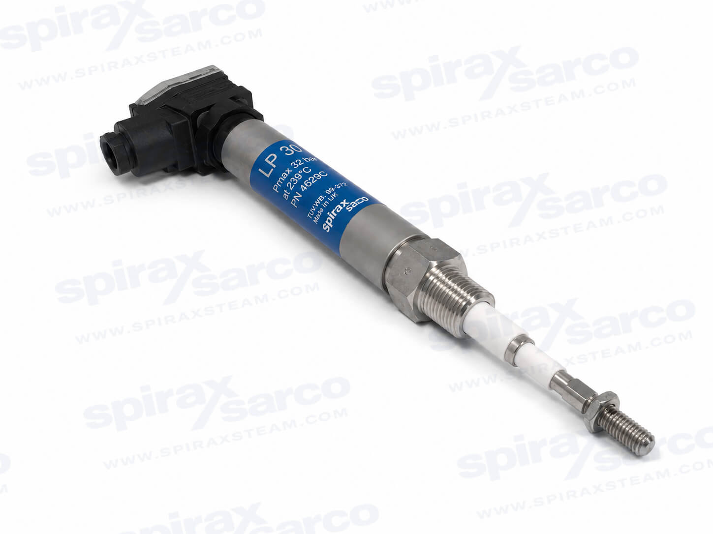
Boiler controls and systems > Level controls
LP30 Self-monitoring Level Probe
The LP30 is a conductivity level probe from Spirax Sarco that gives a high integrity, self-monitoring low level alarm signal on a steam boiler. A comparator tip cancels the leakage to earth caused by scale, dirt and moisture. With an LC3050 controller the system is certified to IEC 61508 at Safety Integrity Level 2 in a 1oo1 architecture and Level 3 in a 1oo2 architecture.
Quick facts
The Spirax Sarco LP30 is a conductivity level probe that provides a high integrity, self-monitoring low level alarm signal, normally on a steam boiler. It is a sensing element rather than a controller: on its own it does not modulate feedwater or drive a burner. What it does is tell a level controller whether water is still covering the alarm point, and it is built so that the system can prove the sensing chain is still working instead of assuming that it is.
The probe is a two-part assembly. A probe body carries a removable cable socket, and a separate probe tip screws into the body and is retained by a pin and a lock-nut. Because the tip is a replaceable, cut-to-length item, one body serves alarm points at different heights: the switching level sits at the extreme end of the tip, which is trimmed on site so that this end lands at the level the boiler needs. Tips are supplied in 500 mm (19.7"), 1 000 mm (39.4") and 1 500 mm (59") lengths, with a ½" BSP taper connection as standard or a ½" NPT taper connection on the UL/FM version.
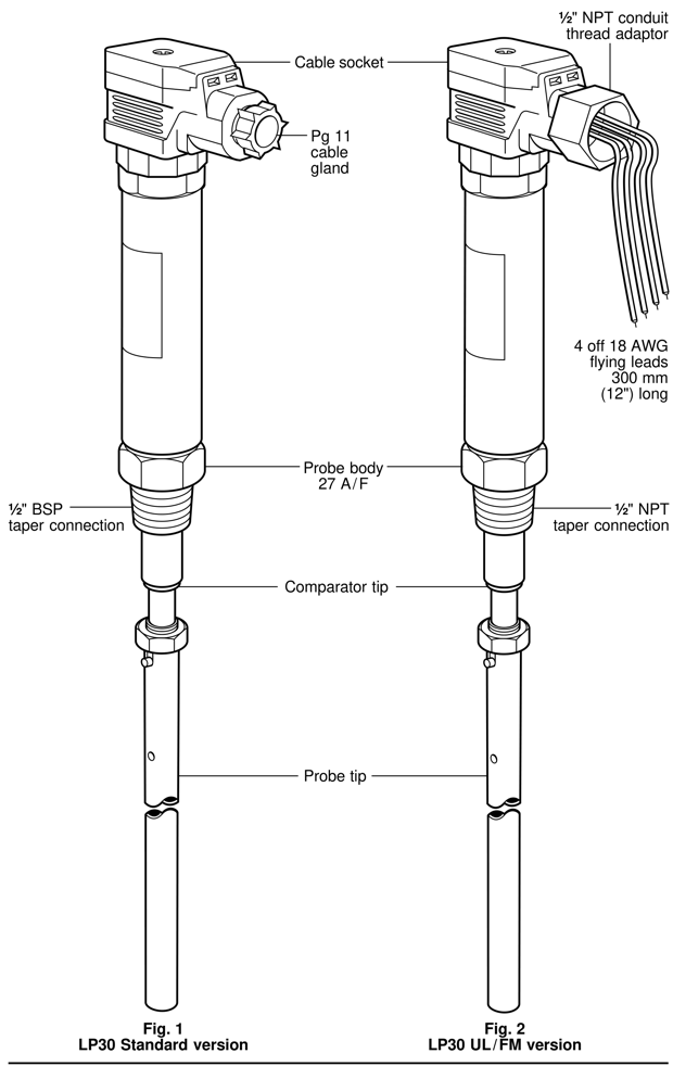
The LP30 works on the conductivity of the boiler water. The level sensing tip is immersed under normal running conditions, and the water provides a low resistance path to earth through the probe body. When the water level falls below the end of the tip, that resistance to earth becomes high, and the controller reads the change as a low level alarm.
What separates the LP30 from a plain conductivity electrode is the second, shorter element on the same assembly: the comparator tip. Scale, dirt and internal moisture all allow a small leakage current to earth, and on a single-electrode probe that leakage looks exactly like water still covering the tip. The comparator tip measures that leakage and cancels it out, so the low water alarm is still given even when the probe has been in service long enough to foul. That is the sense in which the probe is self-monitoring rather than merely conductive.
The rest of the integrity comes from the controller, which energises the probe, compares the resistance to earth against a set limit and raises the alarm once the resistance moves beyond it. A cyclic self-test inside the controller checks the probe, the cable and the electronics every few seconds, so a fault shuts the burner down rather than silently removing the protection.
A low water level is the most serious fault a shell boiler can suffer, and the protection is only worth having if it can be relied on when it is needed. The Spirax Sarco LP30 is the probe half of a system assessed as a functional safety device rather than a simple switch: paired with the appropriate controller it is certified to IEC 61508, reaching Safety Integrity Level 2 in a 1oo1 architecture and Level 3 in a 1oo2 architecture, and it is treated as a safety accessory in Category 4 of the Pressure Equipment Directive. The 1oo2 arrangement is the normally recommended one, with two separate controllers and two separate probes, so that a single failure in one channel cannot remove the protection.
That is the practical reason for choosing a self-monitoring probe rather than a plain electrode. Because the system detects its own faults and shuts the boiler down safely, many national standards allow a boiler fitted with high integrity, self-monitoring controls to run without a trained boiler attendant being on site at all times. The controller is a separate product with its own instructions: the current partner is the LC3050 level controller, certified to IEC 61508 when used with the LP30, while older installations use the LC3000, which the LP30 installation and maintenance instructions were originally written against. The same controller also accepts the LP31 high level probe where a high water alarm is required.
Most shell boilers carry two low level alarms rather than one. The first is a warning that the feedwater supply is not keeping up; the second is the lockout that shuts the burner down before the crown of the furnace is uncovered. The LP30 is used for both duties, and the normal arrangement is two completely independent probes, each in its own protection tube inside the boiler shell and each wired to its own controller. Keeping the channels physically separate is what makes the second alarm independent of the first, since a shared tube would let one blockage disable both. The wider subject is covered under water level alarms.
The alarm levels are not read straight off the gauge glass. In most shell boilers the water swells when the boiler is firing, so the true level is higher than the gauge glass suggests; the difference can reach 50 mm (2") in a very large boiler and is around 10 mm (3/8") in a small one. A second low alarm set close to the bottom of the gauge glass with the boiler cold will therefore rise well clear of it once the boiler is firing.
For that reason the second low level alarm should be set well above the bottom of the gauge glass with the boiler cold, and the first low level alarm is then set about 20 mm (¾") above the second. Where the boiler manufacturer has published working and alarm water levels, those figures take precedence.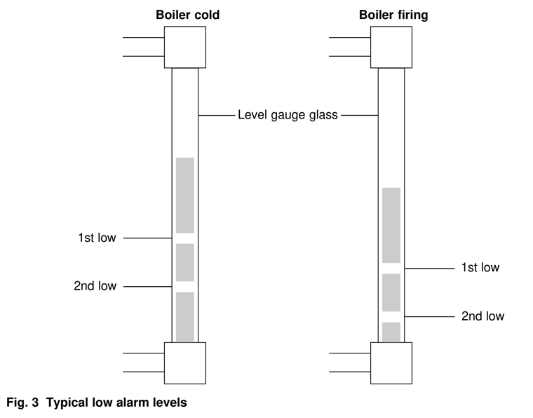
An LP30 used for low level alarm duty on a steam boiler must be installed in a protection tube. The tube gives the probe a relatively steady water level to work against, shielding it from the turbulence and surging inside the boiler shell, and two separate tubes are needed where two alarms are fitted. Dimensions can be varied to suit the application, but a tube bore of at least 80 mm (3") is recommended, and the tube should reach at least 40 mm (1 9/16") deeper internally than the end of the probe so that the tip has room to clear it.
Several other conditions apply. The probe should be positioned at least 1 m (39") away from any safety valve or steam take-off, because the localised water level near those connections is disturbed. Flange lagging is recommended, particularly on larger boilers or where the working pressure is above 10 bar g (145 psi g), but the probe itself must not be lagged, and the vent and drain holes in the probe body must be left clear. The probe is normally mounted vertically; where the tip is no longer than 500 mm (20"), it may be inclined by up to 45° from the vertical.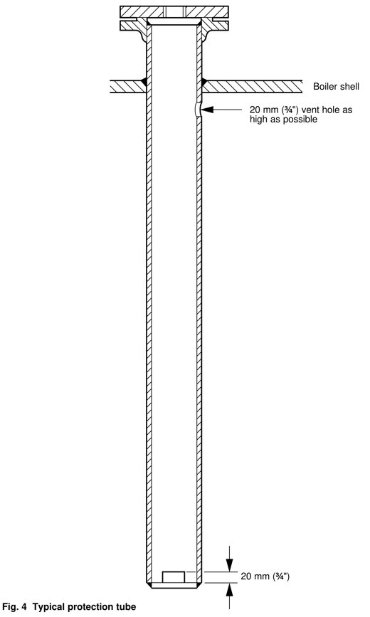
Standards also require the probe tip to keep at least 14 mm (9/16") of clearance from any part of the boiler or protection tube. The LP30 is supplied with a documented procedure for proving that it does, using a pair of checking wires fitted near the end of the tip and an insulation resistance tester. The test is carried out on initial installation and again every time the probe is removed, and the checking wires must be taken off before the boiler is commissioned because leaving them in place can stop the low water alarms from operating. Before a boiler runs unsupervised, the low alarms themselves must be functionally tested by lowering the water level. The general procedure is set out under installation of level controls.
The LP30 has a nominal pressure rating of PN40 and is suitable for boiler pressures up to 32 bar g (464 psi g) at a maximum temperature of 239 °C (462 °F). It is designed for a maximum cold hydraulic test pressure of 60 bar g (870 psi g), the maximum ambient temperature at the probe is 70 °C (158 °F), the cable socket is rated IP65, and the probe cable may run up to 50 m (164 ft) to the controller.
The standard LP30 uses a ½" BSP taper connection with a DIN 43650 cable socket and a Pg 11 cable gland, and its connector block can be rotated in 90° steps to suit the cable route. The UL/FM version uses a ½" NPT taper connection with a ½" NPT conduit thread adaptor carrying four 18 AWG flying leads, and its connector block cannot be rotated. The wiring arrangements and cable types are set out in the installation instructions below.
All the wetted and structural parts are austenitic stainless steel: the probe body is to BS EN 10088-3 (1.4306), and the outer sleeve, comparator tip and probe tip are Type 316L. The cable socket and terminals are polyamide, the nameplate is polycarbonate, the gasket is silicone rubber, and the primary and secondary insulators are PTFE to BS 6564 Grade UA Type 1.
The LP30 is the low level alarm probe of its family, and the LP31 is the matching high water level probe for the same controller. Outside the United States and Canada the equivalent low level alarm probe in the international range is the LP40, which works with a level switch rather than a level controller; the LP30 and LP40 share the same tip lengths and the same pressure and temperature limits but are not interchangeable items.
The LP30 is also not the right probe for every level duty. Where a continuous level signal is needed for modulating feedwater control rather than a fixed alarm point, the capacitance probes in the range are used instead, and where a simpler conductivity electrode will do without the self-monitoring comparator tip, the on/off conductivity probe is the lower-cost route. The other probes and controllers in the family are listed under level controls, and the selection logic behind them is discussed under level control applications.
Two further limits are worth stating. The LP30 must not be installed outdoors without additional weather protection, and as a safety accessory rather than a general purpose level instrument its selection, installation and testing have to follow local or national standards and the boiler manufacturer's own specification. Where the plant priority is boiler water quality rather than level protection, the TDS blowdown controls range addresses that duty, and the full boiler controls and systems range shows how the two fit together in a boiler house.
The Spirax Sarco LP30 is a conductivity level probe with a comparator tip that makes it self-monitoring, used with a compatible level controller to provide high integrity low level alarm protection on a steam boiler. It is specified by the connection form, the tip length and the alarm level the tip is cut to, and it is installed in a protection tube with at least 14 mm of clearance that has to be proven by test. Two independent probes and controllers give the first and second low alarms that a shell boiler normally needs. The technical data and the installation and maintenance instructions reproduced below carry the full limits, the wiring arrangements, the cutting procedure and the safety conditions.
This fragment preserves the published technical information for the LP30 high integrity low level alarm probe. The description, features, limiting conditions, materials, dimensions, weights and ordering information are taken from the LP30 technical information sheet TI-P402-43, AB Issue 8. The probe and controller comparison tables and the system description are taken from the Spirax Sarco electronic steam boiler controls literature SB-GAB-22, AB Issue 1, which is issued for the whole level control range; the LP30 row is the one to read for this product, and the controller data covers the LC3050, the current partner for the LP30. Local regulations may restrict the use of this product to below the conditions quoted, and in the interests of development and improvement Spirax Sarco reserves the right to change the specification without notice.
The Spirax Sarco LP30 level probe is used with a Spirax Sarco LC3050 level controller to provide a high integrity, self-monitoring low level alarm signal, usually in a steam boiler. It consists of a probe body with a removable cable socket, and a separate screw-on probe tip. The probe tip is threaded into the probe body and is retained by a lock-nut and pin, and the earth return path is formed through the probe body.
Under normal operating conditions the probe tip is partially immersed and the resistance to earth is low. When the water level falls below the probe tip the resistance to earth becomes high, causing the controller to give a low water level alarm signal.
The comparator tip compensates for any leakage to earth caused by scale, dirt or internal moisture, ensuring that the correct low level alarm signal is still detected even under adverse conditions.
500 (19.7"), 1 000 (39.4") and 1 500 (59").
| Parameter | Value |
|---|---|
| Nominal pressure rating | PN40 |
| Maximum boiler pressure | 32 bar g (464 psi g) |
| Maximum temperature | 239 °C (462 °F) |
| Maximum cold hydraulic test pressure | 60 bar g (870 psi g) |
| Maximum ambient temperature | 70 °C (158 °F) |
| Maximum probe cable length | 50 metres (164 ft) |
| Cable socket protection rating | IP65 |
| Item | Part | Material |
|---|---|---|
| 1 | Probe body | Austenitic stainless steel BS EN 10088-3 (1.4306) |
| 2 | Outer sleeve | Austenitic stainless steel Type 316L |
| 3 | Nameplate | Polycarbonate |
| 4 | Cable socket and terminals | Polyamide |
| 5 | Gasket | Silicone rubber |
| 6 | Comparator tip | Austenitic stainless steel Type 316L |
| 7 | Primary and secondary insulators | PTFE BS 6564 Grade UA Type 1 |
| 8 | Retaining pin | Austenitic stainless steel Type 302/304 |
| 9 | Probe tip | Austenitic stainless steel Type 316L |
| 10 | Lock-nut | Austenitic stainless steel BS 6105 A4 80 |
| Dimension | mm (inches) |
|---|---|
| Cable socket removal distance | 15 (0.6") |
| Length from the cable socket to the body hexagon | 210 (8.3") |
| Length from the cable socket to the end of the body assembly | 295 (11.6") |
| Connection thread length | 55 (2.2") |
| Body hexagon | 27 A/F |
| Probe tip diameter | Ø10 (0.4") |
| Probe tip length | 500 (19.7"), 1 000 (39.4") or 1 500 (59") |
| Process connection | ½" BSP taper; ½" NPT also available |
| Probe tip length | Probe body | 500 mm (19.7") | 1 000 mm (39.4") | 1 500 mm (59") |
|---|---|---|---|---|
| Weight | 0.51 (1.1) | 0.32 (0.7) | 0.63 (1.4) | 0.92 (2.0) |
| Probe | Probe type | Control characteristic | Probe process connection | Nominal length | Body design rating |
|---|---|---|---|---|---|
| LP10-4 | Conductivity | On / off | 1" BSP taper 1" NPT | 95 mm to 2 095 mm (3.75" to 82.5") | 464 psig @ 462 °F |
| LP20 / PA20 and LP20 / PA420 (NB optional PA420 preamplifier) | Capacitance | Adjustable on / off Modulating | ½" BSP taper ½" NPT | 370 mm to 1 500 mm (14.5" to 59") | 464 psig @ 462 °F |
| LP30 | Conductivity | High integrity Limiter Low alarm | ½" BSP taper ½" NPT | 500 mm (19.7") 1 000 mm (39.4") 1 500 mm (59") | 464 psig @ 462 °F |
| LP31 | Conductivity | High integrity Limiter High alarm | ½" BSP taper ½" NPT | 500 mm (19.7") 1 000 mm (39.4") 1 500 mm (59") | 464 psig @ 462 °F |
The LP30 is used with a self-monitoring level controller. The LC3050 is the current partner; the data below is the published controller information from the same source.
| Level controller | Input signal range | Control characteristic | Communication | Mounting options | Enclosure rating |
|---|---|---|---|---|---|
| LC3050 | Minimum 30 µS / cm or 30 ppm @ 25 °C (77 °F) | High integrity Limiter Low alarm High alarm | Intercontroller infrared | DIN rail Panel Chassis | IP65 (panel mounted) |
To protect a steam boiler from low water conditions, select the LP30 conductivity probe and LC3050 controller. This system monitors the water level on the probe tip, where resistance to earth is low. If the water level falls below the tip, resistance to earth becomes high, activating the low level alarm and shutting down the boiler.
This system enables operators to increase boiler house automation for greater productivity without sacrificing safety. High integrity, self-monitoring alarms give warnings of system faults and allow safe shutdown of plant.
The system normally consists of two completely independent self-monitoring LP30 probes for the 1st and 2nd low water level limiters. Each probe must be mounted in a separate protection tube within the boiler shell and connected to its own LC3050 controller.
A cyclic self-test facility in the LC3050 controller checks the integrity of the probe cable and electronics every few seconds. It will activate the alarm and shut down the burner if a fault should occur. The system will detect both open circuit and short circuit conditions in the cable.
Many National Standards state that boilers fitted with high integrity, self-monitoring controls can be run without the need for a trained boiler attendant to be on site at all times.
The LC3050 and LP30 system has third party approval as suitable in demand and continuous mode to a safety integrity level of SIL2 when used in 1oo1 architecture and SIL3 when used in 1oo2 architecture, meeting the requirements of IEC 61508-2:2000 as quoted in this source.
Example: 1 off Spirax Sarco LP30 self-monitoring level probe, LP30 probe tip 1 000 mm.
This fragment preserves the installation and maintenance instructions for the LP30 from IM-P402-44, AB Issue 13. The document is issued for the LP30 self-monitoring level probe, which is used with the Spirax Sarco LC3050 level controller to provide a high integrity, self-monitoring low level alarm signal, usually in a steam boiler. Safe operation can only be guaranteed if the product is properly installed, commissioned, used and maintained by qualified personnel in compliance with the operating instructions.
Your attention is drawn to Safety Information Leaflet IM-GCM-10, as well as to any National or Regional regulations.
The product is designed and constructed to withstand the stresses encountered in normal use. Using the product for any purpose other than that for which it is intended, or installing it incorrectly without following these installation and maintenance instructions, may result in damage to the product and could cause injury or loss of life.
The LP30 level probe and the LC3050 level controller both comply with the EU Pressure Equipment Directive and carry the CE mark where required. They are classified as safety accessories and fall within Category 4 of the Directive.
Warning: if the product is not used in the manner indicated in these instructions, the protection it provides may be impaired.
Compliance with the operating instructions, and correct installation, commissioning, use and maintenance by suitably qualified personnel, is the only guarantee of safe operation of this product (see Section 1.11). Installation must also comply with the relevant pipeline and plant construction and safety instructions, using suitable tools and the necessary safety equipment.
After installation, ensure that adequate access is available. If necessary, provide a safe working platform before working on the product, and arrange suitable lifting equipment where required.
Ensure that there is adequate lighting, particularly where detailed or intricate work is required.
Consider in advance what is in the pipeline, or what may have been in the pipeline at some previous time. Beware of flammable substances, substances hazardous to health, and substances at high or low temperature.
Consider the risk of explosion, lack of oxygen (for example inside tanks or in low-lying areas), dangerous gases, extremes of temperature, hot surfaces, fire hazard (for example during welding), excessive noise and moving machinery.
Understand how the complete system works. Before carrying out any operation, such as closing an isolation valve or operating an electrical switch, consider whether it could put any other part of the system, or any other personnel, at risk. Dangers include vent pipes or protective devices being isolated, or controls and alarms being rendered ineffective. Open and close isolation valves slowly to avoid system shocks.
Ensure that the system pressure is isolated or completely vented. Consider double isolation (double block and bleed) and the locking or labelling of closed valves. Never assume that the system has been fully depressurised simply because the pressure gauge indicates zero.
After isolating the product, allow it to cool to room temperature to avoid the danger of burns.
Before starting work, ensure that suitable tools and spare parts are available. Use only genuine Spirax Sarco spare parts.
Consider whether the operator or others in the vicinity should be provided with protective clothing to protect against hazards such as chemicals, high and low temperature, radiation, noise, falling objects, and dangers to eyes and face.
All work must be carried out by suitably competent personnel, or under their supervision. Installation and operating personnel must be trained in accordance with the product's installation and maintenance instructions so that they are able to use the product correctly.
Where a formal 'permit to work' system is in force, it must be complied with. Where no such system is in force, the responsible person should be aware of the nature of the work and, where necessary, should arrange to have an assistant whose primary responsibility is safety. Post warning notices where necessary.
Manual handling of large or heavy products presents a risk of injury. Lifting, pushing, pulling, carrying or supporting a load by bodily force can cause injury, particularly to the back. Consider the task, the individual, the load and the working environment, and adopt a handling method appropriate to the site conditions.
In normal use the external surfaces of this product may be very hot. The product cannot be self-drained, so take care when dismantling or removing it from its installed position (refer to the maintenance instructions).
Provision must be made to protect products which are not self-draining against frost damage in environments where they may be exposed to temperatures below freezing point.
The product must be selected, installed, operated and tested in accordance with:
Two independent water level limit/alarm systems must be installed on a steam boiler. The level probes must be installed in separate protection tubes or chambers, with sufficient space at the probe tip and at the bottom of the probe.
Each probe must be wired to its own independent controller. On a low alarm, the alarm relay must cut the boiler heating system.
The high water alarm must be part of the water level control, or a separate system. Where safety requirements demand it, a separate high water alarm system must be installed. In this case, on a high water alarm the relay must cut both the boiler feedwater and the heating system. All boiler water level limit/alarm systems must be functionally tested at regular intervals.
A suitable water treatment regime must be used to ensure continuous safe and correct operation of the water level control and limiting systems. Consult a reputable water treatment company.
This product is recyclable and, provided it is disposed of correctly, no environmental hazard is anticipated.
Customers and stockists are reminded that, under UK and EC Health, Safety and Environment legislation, when returning products to Spirax Sarco they must provide information on any hazards and the precautions to be taken arising from contamination residues or mechanical damage which may present a health, safety or environmental risk. This information must be provided in writing and must include data relating to any substance identified as hazardous to health and safety.
The Spirax Sarco LP30 level probe is used with the Spirax Sarco LC3050 level controller to provide a high integrity, self-monitoring low level alarm signal, usually in a steam boiler. It consists of a probe body with a removable cable socket, and a separate screw-on probe tip. The tip is retained with a roll pin, and held in place with a lock-nut. Two level probes and controllers are normally installed on each boiler to provide two independent low alarms. In many countries this provides first low alarm and second low alarm. The probe is suitable for boiler pressures of up to 32 bar g (464 psi g).
500 mm (19.7"), 1 000 mm (39.4") and 1 500 mm (59").
| Parameter | Value |
|---|---|
| Nominal pressure rating | PN40 |
| Maximum boiler pressure | 32 bar g (464 psi g) |
| Maximum temperature | 239 °C (462 °F) |
| Maximum ambient temperature | 70 °C (158 °F) |
| Maximum cold hydraulic test pressure | 60 bar g (870 psi g) |
| Parameter | Value |
|---|---|
| Maximum probe cable length | 50 metres (164 ft) |
| Cable socket protection rating | IP65 |
The probe has a level sensing tip (probe tip) and a comparator tip. The earth return path is via the body connection.
Under normal operating conditions, the probe tip is immersed, and the resistance to earth is low. When the water level drops below the probe tip the resistance to earth becomes high, causing the controller to give a low level alarm signal.
The comparator tip compensates for any leakage to earth caused by scale, dirt, or internal moisture, ensuring a low water alarm signal even under adverse conditions.
A DIN 43650 cable socket and a Pg 11 cable gland are supplied with each LP30 unit. For the UL/FM version, a ½" NPT conduit thread adaptor with four flying leads is supplied instead.
Warning: it is essential that the probe tip does not touch any part of the boiler. Standards require that the tip is at least 14 mm (9/16") from the protection tube, and this must be checked when the probe is installed. See Section 5, 'Probe clearance test procedure'.
Before proceeding with any installation or maintenance read Section 1, 'Safety information'.
When the probe is to be installed in the boiler, ensure it is positioned at least 1 metre (39") from any safety valve or steam take-off, as increased localised water levels may occur.
In most shell boilers the water will 'swell' when it is firing, such that the actual water level will be higher than the level shown in the gauge glass. In practice this can be up to 50 mm (2") in very large boilers reducing to about 10 mm (3/8") in smaller ones. We recommend, therefore, that the second low level alarm should be well above the bottom of the gauge glass when the boiler is cold, as this will reduce when the boiler is firing. The first low level alarm may be 20 mm (¾") above second low level alarm. Wherever possible the boiler manufacturer should be consulted for advice on the working and alarm water levels.
The probe must be installed in a protection tube when used for low level alarm in a steam boiler. The protection tube provides a relatively steady water level, shielding the probe from the turbulence in the boiler. Two separate protection tubes must be provided, one for the first low level alarm and one for the second low level alarm.
Dimensions and construction may be varied to suit the application, but a tube of at least Ø 80 mm (3") is recommended. A typical protection tube has a 20 mm (¾") vent hole fitted as high as possible.
Flange lagging is recommended, particularly on larger boilers or boilers with a working pressure over 10 bar g (145 psi g). Do not lag the probe.
Do not cover vent and drain holes on the body.
Note: when making flanged or screwed joints, ensure that excess jointing compound does not enter the boiler.
The probe is normally installed vertically, but for probe tip lengths up to 500 mm (20") it may be inclined by up to 45° from the vertical. The low alarm switching level is at the extreme end of the probe tip, which is cut to length to give the required alarm level.
LP30 probe tips are retained by a thread, pin and lock-nut. Earlier probes were retained by two pins only, and a compatible tip is available to special order. For existing installations, it is important to check which type of connection is used before cutting the probe tip to length.
Note: a record sheet is provided for recording this data (see Section 5.3, 'Probe clearance record sheet').
This procedure applies to earlier probes, whose tips are retained by two pins only, rather than by the thread, pin and lock-nut arrangement of the current type.
Warning: ensure boiler or vessel is depressurised and vented to atmosphere before attempting to unscrew or remove the probe.
Refer to the relevant controller documentation/wiring diagram for full information, including screen connection details.
Cabling should be installed in accordance with BS 6739 - Instrumentation in Process Control Systems: Installation design and practice or local equivalent. For US and Canadian installations the probe must be wired in accordance with the National and Local Electrical code (NEC) or the Canadian Electrical code (CEC). Wiring should be carried out using 4 core, 1 mm² (18–16 AWG), high temperature screened cable, with a maximum length of 50 metres (165 ft). Pirelli FP 200 or Delta Crompton Firetuf OHLS are two suitable types for the standard LP30. For the UL/FM version, Class 1 screened cable with a suitable temperature rating (75 °C/167 °F minimum) must be used to connect the terminal box to the controller.
Ensure that sufficient cable length is provided to allow removal of the cable socket and to ensure that no strain is placed on the unit.
To unplug the cable socket, remove the central screw. To gain access to the connector block within the cable socket, remove the central screw and withdraw the hinged cover.
Note: to provide environmental protection the probe is supplied with a gasket between the cable socket and the probe connector. To maintain environmental integrity, ensure the gasket is always present when reconnecting cable socket and that all contact surfaces are clean and undamaged.
The connector block on the standard LP30 may be rotated in 90° steps to facilitate wiring: remove the retaining screw and withdraw socket, then remove the connector block and reposition as required. The connector block is numbered: 1 red probe tip, 2 black comparator tip and 3 black comparator tip, with the yellow earth and the screen.
Note: it is not possible to rotate the connector block on the UL/FM version.
Ensure that the resistance from the probe body to the boiler shell is less than 1 Ω.
Issue 13 also documents the wiring of the standard and UL/FM LP30 to the LC3050 level controller (terminals 50 to 54), alongside the LC3000 arrangement shown in the figure below (terminals 9 to 12).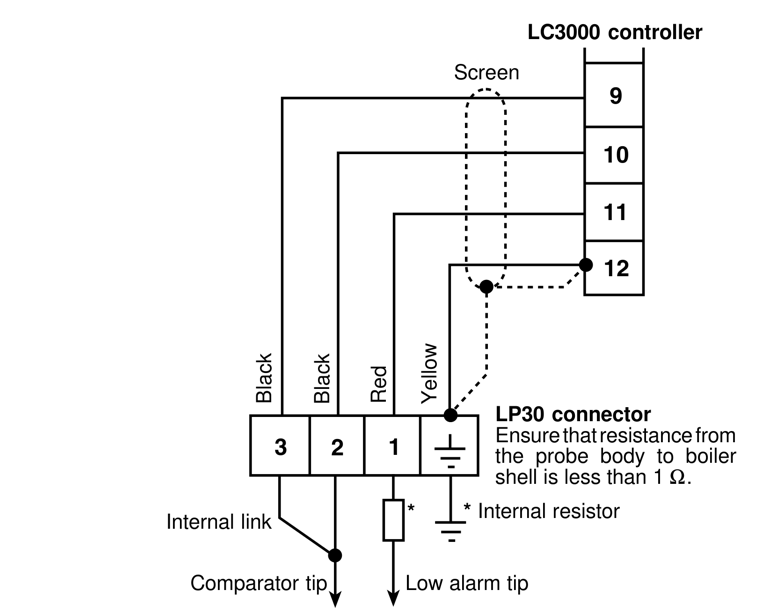
The socket is supplied with four 18 AWG, 300 mm (12") long colour coded flying leads. These are to be cut to length and connected to a suitable metal terminal box. A length of flexible metal conduit is required between the probe and the terminal box to provide environmental protection and easy electrical connection. The cable socket is provided with a ½" NPT conduit adaptor for this purpose.
Warning: the flying leads supplied with the probe are rated to 221 °F (105 °C). This temperature rating must not be exceeded.
The flexible conduit and terminal box are not to incorporate any other control wiring as this may damage or reduce the performance of the product.
It is not possible to rotate the cable socket in 90° steps, as with the non-listed LP30. To do so may damage the internal wiring.
Ensure that any condensation which might build up in the conduit network is prevented from accumulating in the probe cable connector and terminal box.
To ensure safe, correct operation of the system, it is essential that the probe tip does not touch any part of the boiler or protection tube. Standards require that the probe tip has at least 14 mm (9/16") clearance.
This test confirms that the LP30 probe is installed correctly. The test must be done on initial installation, and each time the probe is removed from the boiler, e.g. for annual inspection.
A pair of 'checking wires' are used in conjunction with an Insulation Resistance Tester (meter) to test if there is less than 14 mm (9/16") radial clearance from the tip end. This is indicated by a 'short circuit' (i.e. a reading less than infinity).
When correctly carried out, the test will ensure that the final probe tip position is at least 14 mm (9/16") from the protection tube.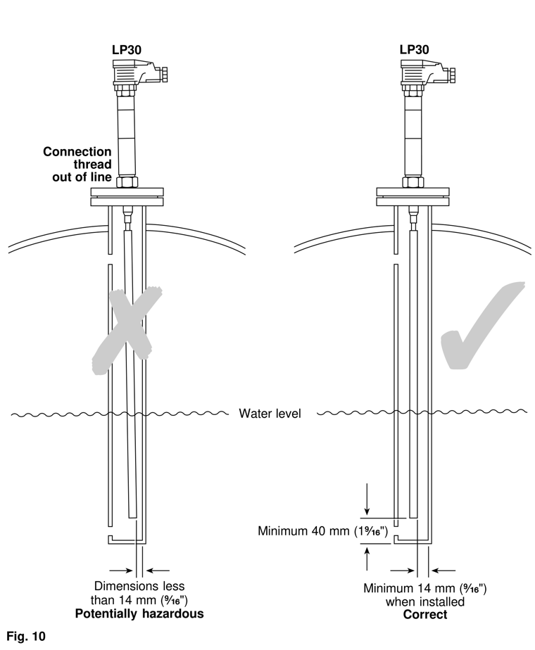
Warning: it is essential to remove the checking wires from the probe before commissioning the boiler or vessel. Failure to do this could lead to the low alarms not working.
If a short circuit was found during the test then further investigation is needed. Some possible reasons are listed below:
We strongly recommend that a record of the probe clearance test is kept, and a record sheet is provided for this purpose. It covers the date, the reason for the test (initial installation or annual inspection), a clearance confirmation that the tip clearance is greater than 14 mm (9/16"), the signature of the person who removed the checking wires, and the verification of an independent assessor (who might be an insurance inspector, for example), confirming that the test has been carried out, that the checking wires have been removed and that the record sheet has been correctly completed by a competent person. The record must be completed each time the probe is fitted or refitted.
No special maintenance is required, apart from an annual inspection and cleaning of the probe assembly. It is particularly important to clean the threaded contact surfaces between the tip extension and the probe central electrode (use fine abrasive paper). More frequent cleaning is recommended where the quality of boiler water might cause a build-up of insulative scale or oxide on the probe.
Clean the probe body with a cloth dampened with deionised water or isopropyl alcohol. Other cleaning agents may damage the product and will invalidate the warranty.
Boiler water level controls, however, do require regular testing and inspection. For specific testing instructions for Spirax Sarco systems please see separate literature.
Use only genuine Spirax Sarco replacement parts. The spares listed below are the only spares available; no other spares are supplied.
| Spare | Stock No. | Pack |
|---|---|---|
| LP30 tip retaining pins | 4024780 | Pack of 10 |
| Clearance checking set | 4024781 | 1 set (2 springs) |
Ordering spares: order spares using the description of the available spare and state the product name. For example: 1 off clearance checking set for the Spirax Sarco LP30 self-monitoring level probe.
LP30 is typically deployed alongside a self-monitoring level controller such as the LC3050 and its alarm circuits. Consider confirming the complete level management solution during selection.
Return to the level controls route to continue reviewing the broader boiler level management product path.
Review TDS blowdown controls when the project also needs boiler water quality management or blowdown control.
Use the automatic level control knowledge page when the project requires a deeper understanding of boiler level control principles.