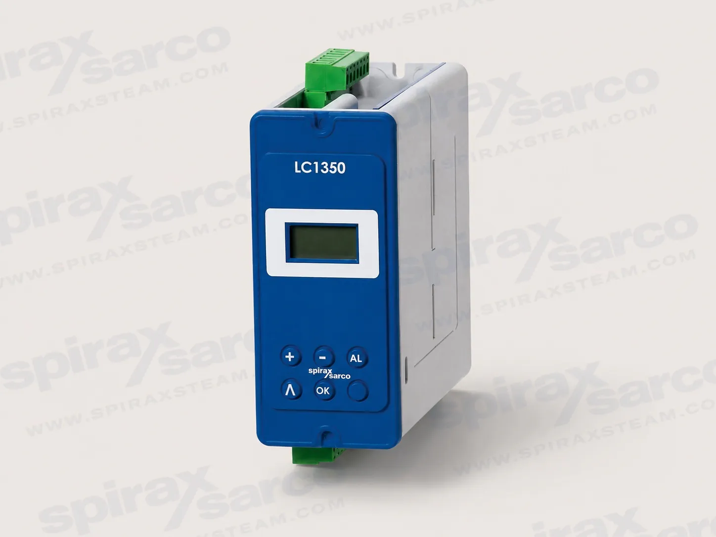
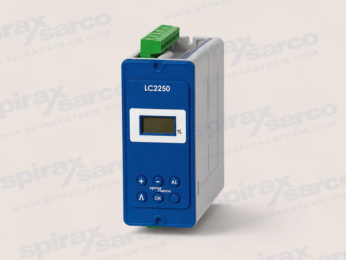
LC2650 Level Controller
LC2650 is a configurable level controller for conductive liquids in boilers, tanks and vessels, with two high/low alarm channels, on/off or modulating control, and 1-6 V or 4-20 mA level inputs.

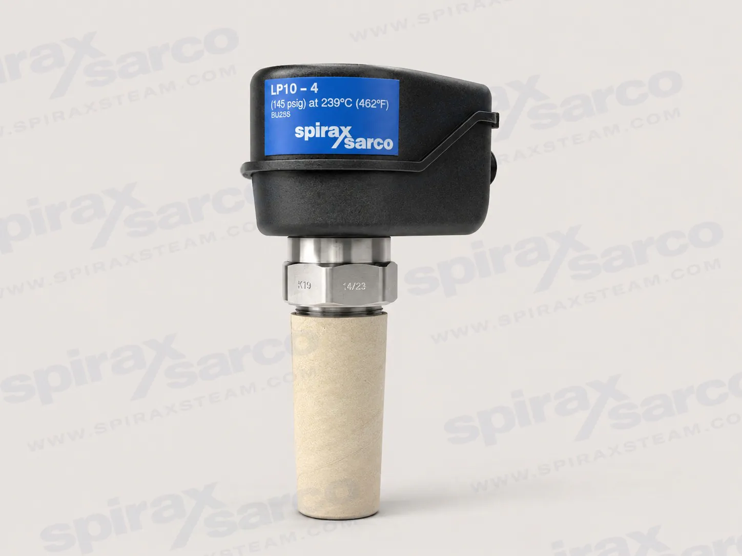
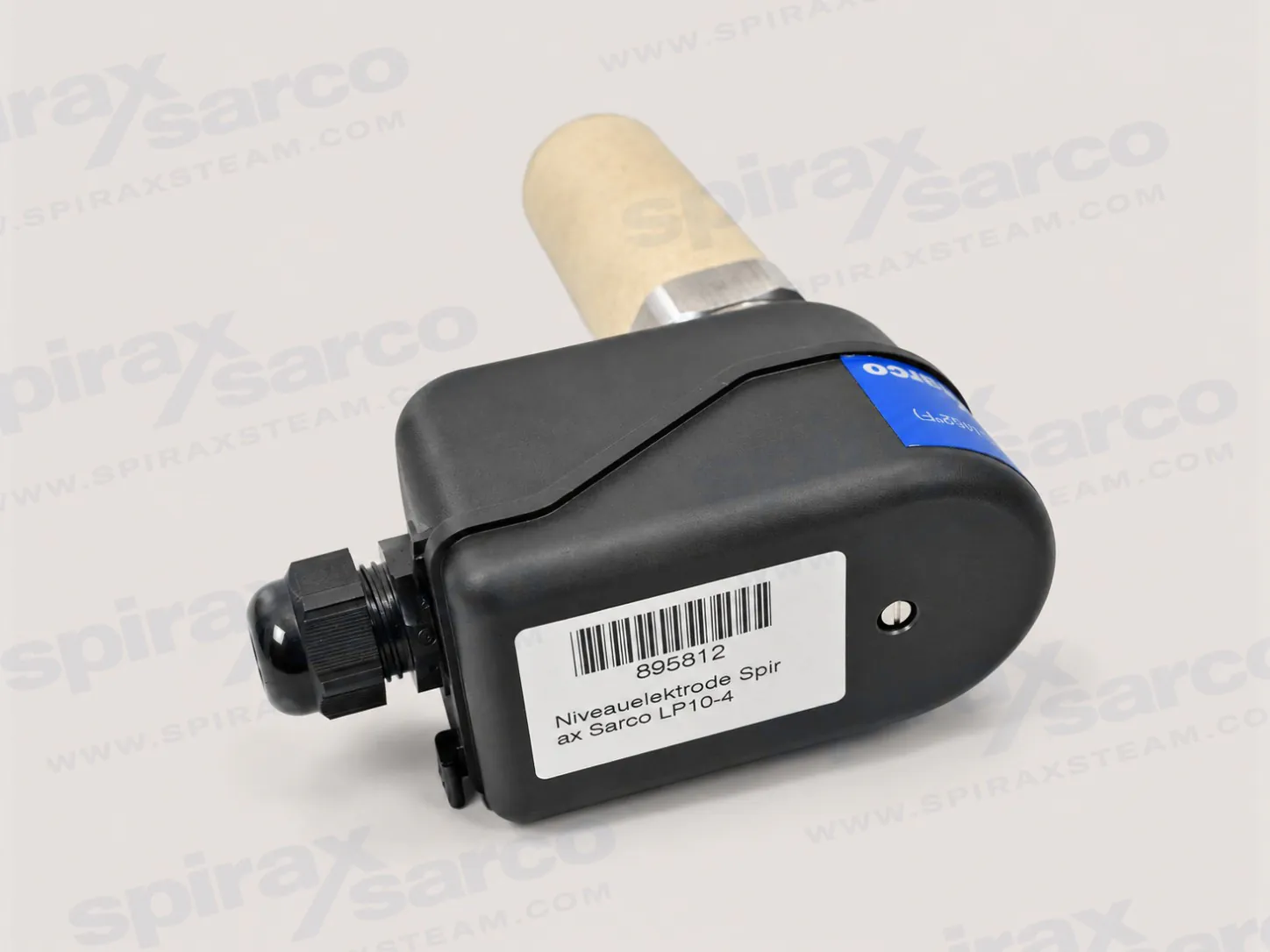
LP10-4
LP10-4 Conductivity Level Probe
LP10-4 is a four-tip conductive level probe for on/off level control and alarms in boilers, tanks and other vessels, with detachable tips, defined sensing depths and BSP or NPT connections.
Spirax Sarco LP10-4 is a four-tip conductivity level probe for on/off level control and alarm functions in steam boilers, tanks and other vessels containing conductive liquid. The probe works with a suitable level controller, such as the documented LC1300 arrangement. It gives the controller a clear electrical indication of whether each sensing tip is immersed, allowing the control system to respond to a pump command, a level alarm or another approved plant function.
The product is a sensing element, not a complete level-control or boiler-protection system. Correct application of Spirax Sarco LP10-4 depends on the controller, the probe length, the earth-return arrangement, the protection tube or chamber, wiring and the independent safety functions required by the boiler manufacturer and local regulations. Those surrounding items should be selected and checked as one system before an LP10-4 is ordered.
Each of the four LP10-4 tips is detachable and can be cut to the required switching level during installation. When a tip is immersed in conductive liquid, it completes an electrical circuit to earth. When the liquid falls below that tip, the resistance to earth becomes high. The level controller interprets that change and can distinguish the configured operating and alarm points. Four sensing points allow a single probe to support a typical sequence such as high alarm, pump stop, pump start and low alarm, subject to the controller configuration and the approved boiler-control design.
The probe body is earthed through its threaded connection, with the boiler or tank normally forming the earth-return path. If the vessel is concrete, plastic or otherwise non-conductive, one tip can be assigned as the earth return or a separate earth rod or plate can be provided. The earthing method must be confirmed for the actual vessel. In a boiler, the installation and safety guidance must be followed rather than assuming that the boiler wall alone is an acceptable protective arrangement.
The probe tips are supplied in four colour-coded circuits and are supported and electrically separated by PEEK steadies. The steadies are essential: omitting them can allow the tips to short together or contact a protection tube. A 1,000 mm tip set is the standard arrangement. Two sets can be joined when the required sensing length is greater, up to a documented maximum of 2,095 mm. The shortest sensing depth is 75 mm, so the required operating levels should be measured before the tips are cut.
Spirax Sarco LP10-4 is suited to conductive water-level duties where discrete switching points and alarm states are required. Typical applications include steam boilers, feedwater or condensate tanks, and process vessels that contain a sufficiently conductive liquid. The probe can be installed directly in a vessel or in an external chamber. For a boiler or a tank with strong turbulence, the technical information recommends a protection tube with at least 80 mm nominal bore. The tube, chamber and available immersion length must leave enough clearance around the tips for stable sensing and for safe removal.
In a boiler, level indication and safety logic need particular care. The normal control function must not be treated as the only low-water protection. Applicable regulations and the boiler maker's instructions may require two independent level-limit or alarm systems, with separate sensing, protection and control arrangements. Every alarm and protective circuit must be tested at the intervals required for the plant. Water treatment also matters: scale or contamination on a probe is a warning that deposits may be forming elsewhere in the boiler and that the treatment regime needs attention.
LP10-4 is not intended for an unprotected outdoor installation. Weather, condensation, contamination and freezing can affect the probe and its wiring. Additional environmental protection is required outside, and the complete enclosure and cable entry should be chosen for the actual site. The probe is designed for high-temperature service, but the stated pressure and temperature limits remain hard boundaries for selection.
The LP10-4 technical information gives a nominal PN40 pressure rating, a standard maximum pressure of 32 barg and a standard maximum temperature of 239°C. The French installation guide separately identifies lower limits for the UL-certified condition: 30 barg and 235°C. These are condition-specific limits, not values to be combined. Confirm the certification variant, destination market and complete system design before selection. Ambient temperature is documented from -20°C to 70°C, and the probe body has an IP54 protection rating.
The body is austenitic stainless steel to BS EN 10088-3 (1.4306), while the sensing tips are Type 316/316L stainless steel. PFA sleeves insulate the tips, PPS forms the upper and lower housings, and a PEEK Grade 450G steady provides the support and separation needed along the sensing length. The cable gland is polyamide and its support pad is a thermoplastic elastomer. These material details are useful when checking compatibility with the liquid, temperature, cleaning regime and the enclosure around the probe.
When the probe is used with an LC1300 controller, the minimum conductivity stated in TI-P402-91 is 1 µS/cm at 25°C. Conductivity can change with temperature and water treatment, so the value should be treated as a selection check rather than a substitute for measuring the real liquid. The controller input, cable construction and earthing arrangement must all be compatible with the chosen sensing method.
Specify the threaded connection when the probe is ordered. The documented options are BSP Rp1, described as a 1 inch BSP tapered connection, and 1 inch NPT. The NPT version is identified as UL61010-approved, not CE marked and not suitable for Europe. Do not treat BSP and NPT as interchangeable: the flange, cover, protection tube and maintenance tools must match the selected thread.
Measure the operating levels from the probe body and mark each tip before cutting. Keep at least 15 mm of tip beyond the connection or support arrangement, keep the shortest tip at least 75 mm long, and support long tips so that an unsupported length does not exceed the installation guide's limit. Maintain the probe while fitting long tips so they do not bend or twist, and tighten the supplied connectors and lock-nuts fully. The tip steadies should sit above the water level where possible and must support and separate the active tips.
Use the high-temperature screened cable, connectors and functional-earth arrangement specified for the selected controller. The TI lists a 30 m probe-to-controller cable length, while the installation guide describes a 100 m maximum for its high-temperature screened cable arrangement. Because these statements are tied to the document and controller arrangement, the responsible engineer should confirm the governing value before commissioning. Keep signal wiring separate from power wiring and do not create an unintended earth loop at the controller.
With those checks complete, Spirax Sarco LP10-4 provides a straightforward four-point conductive signal for level control and alarm logic. Its detachable tips, defined sensing range, stainless-steel construction and documented boiler limits make it practical for engineered boiler-house and conductive-liquid vessel systems. For the wider selection context, see the level controls category and confirm the controller, protection and safety architecture for the specific installation.
LP10-4 is a four-tip conductive level probe used with the Spirax Sarco LC1300 level controller for on/off level control and alarm functions in steam boilers, tanks or other vessels. The probe body is earthed through its screwed connection and the vessel normally forms the earth return path. In a concrete or plastic tank, one tip may be used as the earth return or a separate earth rod or plate may be provided.
Each of the four level-sensing tips is detachable and cut to the required length during installation. When a tip is immersed in conductive liquid it completes an electrical circuit to earth. When the level drops below the tip, resistance to earth rises and the controller receives the level-state change. Tips are supplied separately from the probe body where stated by the ordering information.
| Parameter | Standard condition | UL-certified condition where stated |
|---|---|---|
| Nominal pressure rating | PN40 | PN40 |
| Maximum allowable pressure | 32 bar g (464 psi g) | 30 bar g (French IM-P402-92 condition) |
| Maximum allowable temperature | 239 °C (462 °F) | 235 °C (French IM-P402-92 condition) |
| Maximum ambient temperature | 70 °C (158 °F) | 70 °C (158 °F) |
| Minimum ambient temperature | -20 °C (-4 °F) | -20 °C (-4 °F) |
| Protection rating | IP54 | Confirm enclosure and destination-market requirements |
| Maximum sensing depth | 2,095 mm (82.5 in) | 2,095 mm (82.5 in) |
| Minimum sensing depth | 75 mm (3 in) | 75 mm (3 in) |
| Minimum conductivity with LC1300 | 1 µS/cm at 25 °C (77 °F) | Confirm controller documentation |
Condition note: Standard and UL-certified limits are listed separately because the source documents give different UL pressure and temperature values. Select the certification variant and apply the lower applicable limit where required.
| Item | Verified information |
|---|---|
| Standard tip supply | Four detachable tips, each 1,000 mm (39.4 in) long |
| Extended arrangement | Two tip sets may be joined for a maximum probe length of 2,095 mm (82.5 in) |
| Thread options | BSP Rp1 (1 in BSP tapered) or 1 in NPT threaded flange or cover |
| NPT approval boundary | UL61010-approved version; not CE marked and not suitable for Europe |
| Protection tube recommendation | Minimum 80 mm (3 in) nominal bore for boilers or tanks with strong turbulence |
| Outdoor installation | Additional environmental protection is required |
| Cable length | 30 m probe-to-controller in TI-P402-91; the IM wiring arrangement states 100 m for its high-temperature screened cable arrangement. Confirm the governing controller-specific instruction. |
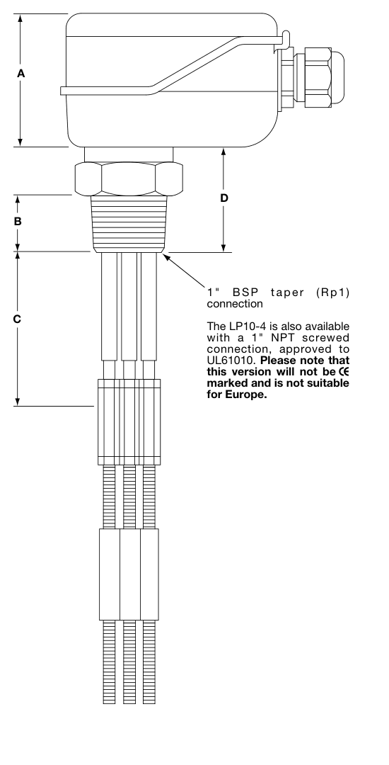
| Dimension or mass | Approximate value |
|---|---|
| A | 60 mm (2.4 in) |
| B | 25 mm (1.0 in) |
| C | 75 mm (3.0 in) |
| D | 50 mm (2.0 in) |
| Weight | 1.15 kg (2.5 lb) |
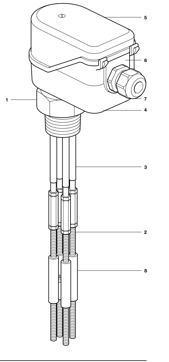
| No. | Component | Material |
|---|---|---|
| 1 | Probe body | Austenitic stainless steel, BS EN 10088-3 (1.4306) |
| 2 | Probe tips | Austenitic stainless steel, Type 316/316L |
| 3 | Tip insulation sleeving | PFA (Perfluoroalkoxy) |
| 4 | Lower housing | PPS (polyphenylene sulphide) |
| 5 | Upper housing | PPS (polyphenylene sulphide) |
| 6 | Gland support pad | Thermoplastic elastomer |
| 7 | Cable gland | PA (polyamide) |
| 8 | Tip steady | PEEK (polyaryletherketone), Grade 450G |
Safety: This technical information does not replace the IM-P402-92 installation and maintenance guide. Isolate, depressurise and cool the system before work, and use competent personnel and genuine replacement parts.
Safe operation can only be guaranteed when LP10-4 is installed, commissioned and maintained by qualified personnel in accordance with this guide and the applicable installation and safety requirements for the pipework, boiler or vessel. Use suitable tools and safety equipment. If the product is installed or used outside these instructions, protection may be impaired and damage or injury may result.
Boiler level-control and alarm systems must be selected, installed, operated and tested in accordance with current legislation and the boiler manufacturer's specifications. Provide the independent level-limit or alarm systems required for the boiler. Use an appropriate water-treatment programme so that the level-control and alarm functions remain reliable.
LP10-4 is a conductive level probe for use with compatible Spirax Sarco controllers, including LC1300. It can be used in boilers, tanks and other vessels containing conductive liquid. The probe has four detachable tips. Cut the tips to the required operating or alarm levels during installation. When a tip is immersed, the resistance to earth is low; when the tip is exposed, the resistance rises and the controller sends the corresponding signal to the pump or alarm circuit.
| Limit | Value |
|---|---|
| Design pressure | PN40 |
| Maximum allowable pressure | 32 bar g standard; 30 bar g for the UL-certified condition stated in this guide |
| Maximum allowable temperature | 239 °C standard; 235 °C for the UL-certified condition stated in this guide |
| Ambient temperature | -20 °C to 70 °C |
| Pollution degree | 3 |
| Minimum conductivity with LC1300 or LC1350 | 1 µS/cm at 25 °C |
Read the safety information before beginning installation or maintenance. The probe may be installed directly in a boiler or tank, or in an external chamber. A protection tube is recommended when it is installed directly in a boiler. Two probes may share one protection tube, but where a boiler requires two low-level alarms the two systems must be completely independent, with independent probes, protection tubes or chambers and controllers. Consult the boiler manufacturer where necessary; the water level shown by a gauge glass can differ from the actual boiler level.
Provide additional weather protection for an outdoor installation. The probe has a BSP Rp1 (1 inch BSP tapered) or 1 inch NPT threaded connection. The tip steadies hold the tips in position and keep them electrically separated. The four 1,000 mm tips are supplied with connectors, lock-nuts and two steadies; two sets can be connected for a maximum probe length of 2,095 mm.
Warning: The steadies are essential parts of the probe. Without them, the tips may short together or contact the protection tube.
Support the probe along its length while installing it, especially when the tips are longer than 1 m. Do not allow the tips to rotate in the probe body while securing the connectors or lock-nuts.
Check that the male and female threads are undamaged. Apply no more than three turns of PTFE tape to the probe thread; do not use paste or adhesive. Fit and tighten the probe by hand first, then use the correct spanner. Never use pipe grips. Do not overtighten: some thread must remain visible on the probe body. If the thread bottoms out or the female thread is outside tolerance, replace or rework the connection rather than forcing the probe.
Before loosening or removing the probe, ensure that the boiler or vessel is depressurised, vented safely and emptied as required. Use the correct size spanner, never pipe grips. Inspect the male and female threads for damage caused by overtightening or galling; replace the probe or connection if damaged.
Electrical work and materials must comply with the applicable EN, IEC and local requirements. Follow the wiring diagram and the instructions for the selected controller.
Use a high-temperature screened five-wire cable (four signal wires plus earth), typically 1 mm². The installation guide gives a maximum distance of 100 m between an LC1300 controller and LP10-4 for this cable arrangement. TI-P402-91 gives a separate 30 m probe-to-controller statement; confirm the exact controller, cable and governing document before commissioning.
Remove the retaining nuts from the upper body to access the crimp connectors. A non-insulated crimp connector is provided for the functional earth and can be connected to an M3 thread. The supplied high-temperature crimp connectors are for 0.25 to 1.6 mm² (16 to 22 AWG) conductors. Do not replace them with standard connectors. Connector set 4024480 is available as a spare. The cable gland can be replaced by a flexible conduit connection such as Pg16, 1/2 inch BSP, 1/2 inch NPT or M20 when the required lock-nut is fitted.
The probe head and wiring can be separated from the lower body by unscrewing the head and pushing the clamp bolt out, without removing the clamp bolt from the head. Do not overtighten the upper-body nut.
The probe earth terminal is primarily a functional earth for draining electrical interference, not a protective earth. Connect the screen as instructed for the controller and ensure the controller common is earthed through the probe and vessel arrangement. Do not connect the controller common to a separate earth near the controller, because an earth loop can reduce performance or damage the product. Verify continuity between the probe body and the vessel or pipework; the guide gives a target well below 1 ohm for the documented arrangement.
LP10-4 needs no special routine maintenance, but boiler level controls must be tested regularly as required by law and the plant's safety procedures. Include the probe in those tests.
Scale warning: Scale on a tip indicates that scale may also be forming in the boiler. Review the water-treatment programme promptly.
Available electrical connector replacement set: part number 4024480. Use genuine replacement parts and follow the controller's commissioning procedure.
Confirm application suitability from this guide, the nameplate and TI-P402-91. Check the fluid, material compatibility and minimum and maximum pressure and temperature. Provide system protection if a product limit is below the system limit or if a failure could create dangerous overpressure or overtemperature.
LC2650 is a configurable level controller for conductive liquids in boilers, tanks and vessels, with two high/low alarm channels, on/off or modulating control, and 1-6 V or 4-20 mA level inputs.
Spirax Sarco LC1350 is an on/off level controller for conductive liquids in boilers, tanks and vessels, with two configurable high/low alarm channels, LP10-4 conductivity-probe input and relay control for a pump or solenoid.
LC2250 is a configurable level controller for conductive liquids in boilers, tanks and vessels. It supports on/off or modulating control, two configurable high/low alarms, and 1-6 V or 4-20 mA level inputs.
The LP30 is a self-monitoring level probe from Spirax Sarco designed for steam boiler level monitoring. With built-in self-diagnostics, it triggers an alarm or safety interlock action when boiler water level falls to a dangerous low point, making it a critical component in boiler level safety protection systems.