
LC3050 high and low level limiter and alarm controller
Spirax Sarco LC3050 is a high and low level limiting monitor and alarm controller for conductive liquids. It is designed for steam and hot water boiler applications, and can also be used for other conductive-liquid level-limiting duties when the liquid meets the documented conductivity requirement. The controller works with a compatible self-monitoring probe to identify a high or low level condition, operate its alarm relays and signal the associated plant protection circuit. For a boiler-house project that needs a clearly defined alarm response rather than ordinary level indication, Spirax Sarco LC3050 provides a dedicated limiting function in a compact panel, DIN-rail or chassis-mounted unit.
The product should be selected as one part of a complete engineered safety system. The controller, probe, protection tube or chamber, alarm relays, burner isolation circuit, water treatment, wiring and proof-test procedure all contribute to the finished function. The installation guide states that most countries require two independent low-water limiting systems on steam boilers. It also requires independent controllers and regularly tested alarm circuits where the system is used for boiler protection. LC3050 is therefore not a substitute for the complete safety design, local regulations or the requirements of the boiler manufacturer and approval authority.
Conductivity sensing for a defined level limit
LC3050 compares the electrical resistance from the probe, through the water, to the boiler or vessel shell. When a change in liquid level causes that resistance to pass the configured limit, an internal timer applies the preset response delay and changes the state of the alarm relay. The normal signal can be used to indicate that the boiler water is within the expected range; an alarm signal can be used to sound an alarm and remove the burner heat supply or another controlled load, subject to the approved plant circuit.
The documented low-level arrangement uses the LP30 low-level probe. A high-level limiting arrangement can use the LP31 high-level probe. The probe is not a page variant of the controller: it is associated equipment whose sensing arrangement and installation position must be selected for the actual boiler or vessel. The source documents describe a compensation tip that helps account for leakage to earth caused by scale, dirt or internal moisture. Probe clearance, earthing and the condition of the protection tube remain critical installation checks.
For steam and hot water boilers, the installation guide gives a minimum liquid conductivity of 30 µS/cm or 30 ppm. Other conductive-liquid applications require the same kind of application review: confirm the liquid conductivity at the operating temperature, the electrode arrangement, the material compatibility and the consequence of a high or low level. A conductivity value alone does not establish a safe alarm point or prove that the complete installation is suitable.
Automatic self-testing and manual proof testing
A key function of the LC3050 is its automatic cyclic test. At intervals of a few seconds, the controller internally simulates a probe fault and checks the integrity of the probe, probe cable and controller. The test is intended to detect open-circuit and short-circuit conditions without interrupting normal level monitoring. During normal level operation, the green LED is illuminated; its brief interruption indicates that the cyclic test is running. If a low or high level condition, or a system fault, is detected, the red alarm LED illuminates and the alarm relays de-energise according to the documented circuit arrangement.
The front-panel AL test button provides a full manual test of the probe, controller and associated circuits. Holding the button for approximately five to six seconds simulates the alarm response so that the boiler panel, alarm lamp, bell, burner isolation and any lockout reset sequence can be checked. The guide also describes an optional external test button. Manual testing is separate from the automatic cyclic test because the self-test does not verify every downstream shutdown action. Proof-test frequency must follow local requirements and the approved safety procedure.
This distinction is important when evaluating the product. The controller can detect defined probe and wiring failures, but the complete safety function also depends on the relay circuit, external actuators, burner controls, operator response and scheduled inspection. For the documented LC3050/LP30 low-level alarm system, the source includes a functional-safety assessment giving SIL2 for a 1oo1 architecture and SIL3 for a 1oo2 architecture, subject to the stated installation, proof-test, lifetime and use conditions. Those claims apply to the assessed system and architecture; they are not an unconditional rating for an isolated controller used outside the documented arrangement.
Clear status indication and controller integration
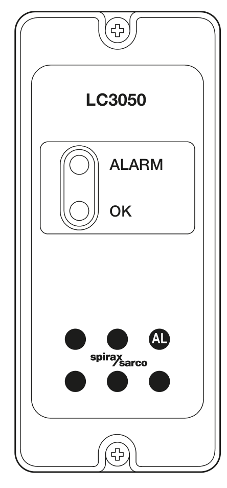
Two front-panel LEDs give operators an immediate status signal: green indicates normal level and red indicates a level alarm or detected system fault. The AL button is deliberately the functional control on the front panel; the other illustrated keypad positions are non-functional. This simple interface suits a limiter whose primary role is to provide an unambiguous normal or alarm state, while the detailed boiler control panel and external alarm circuit provide the wider plant indication.
LC3050 is an infrared slave in the documented controller communication arrangement. Its parameters can be passed through the infrared link to an adjacent compatible controller fitted with an RS485 interface. The installation guide requires the infrared beam between products to remain unobstructed and limits the communication geometry to the documented range and angle. The technical information identifies the IrDA physical layer, 38,400 baud, a 10 cm range and a 15-degree working angle. Communication is an integration aid; it does not remove the need to wire and test the local alarm and shutdown circuits.
Mounting and environmental boundary
The controller can be mounted on a 35 mm DIN rail, a chassis plate or in a panel cut-out. It must be installed vertically, with the green and red indicators visible to the operator. A panel installation needs the documented cut-out, fixing-hole positions and minimum 15 mm spacing between adjacent units for cooling. The unit is sealed and has no replaceable internal parts or switches, so it must not be opened during routine installation or maintenance.
LC3050 is intended for indoor use. The documented ambient range is 0 to 55 °C and the maximum altitude is 2,000 m. The complete installation requires an industrial control panel or fireproof enclosure providing at least IP54 to EN 60529, or an applicable listed UL50/NEMA enclosure type. The IP65 and NEMA Type 4 hose-down statements apply to the front panel within their stated approval scope, not automatically to the complete controller installation. Outdoor use requires additional weather protection, and harsh conditions such as conductive dust, moisture, heat, vibration and electrical interference require a specific enclosure and installation review.
Selection checks before ordering
- Confirm the limiting function. Decide whether the application needs low-level protection, high-level protection or both through separate documented systems. Define what the alarm must isolate or signal and how the plant will return to normal operation.
- Confirm the probe arrangement. Select the LP30 or LP31 arrangement required by the application, verify the probe protection tube or chamber, and confirm electrode clearance, shell bonding and the required cable route.
- Check the liquid. Verify a minimum conductivity of 30 µS/cm or 30 ppm for the documented level input and check the actual fluid, temperature, fouling tendency and water-treatment regime.
- Plan independent protection. For steam boilers, review the requirement for two independent low-water limiting systems, independent controllers, separate probe installations, burner isolation and regular proof testing with the relevant authorities.
- Confirm the supply and relay circuit. Choose the 220/240 Vac or 110/120 Vac setting, confirm the available voltage range, apply the specified 100 mA supply protection and 3 A quick-blow protection for the burner relay circuit, and verify the relay load.
- Check mounting and enclosure. Reserve the vertical DIN-rail, chassis or panel position, keep the indicators visible, maintain cooling clearance, protect the unit from environmental pollutants and keep the infrared path open where controller communication is used.
- Define the test procedure. Include the automatic cyclic test in the operating philosophy, but separately schedule the manual AL proof test and downstream shutdown verification at the interval required by local rules and the safety assessment.
Where LC3050 fits in a boiler level system
Spirax Sarco LC3050 is intended for applications where the consequence of an abnormal water level must be detected and acted upon by a defined alarm circuit. It provides the sensing interface, cyclic integrity checking, front-panel status and dual relay contacts needed for the documented limiter arrangement. The complete design still determines the probe positions, alarm set points, circuit logic, burner interlock, external annunciation, test frequency and response to a detected fault.
Before specifying the controller, review the wider level controls range to confirm that a dedicated limiter is the correct product role. The documented LP30 low-level probe arrangement is the relevant companion reference for the low-water system, while the boiler water level alarms guide provides useful application context for alarm selection and system review.
For projects selecting Spirax Sarco LC3050, the final review should record the exact probe, supply setting, enclosure, relay circuit, safety architecture, proof-test method and local approval requirements. With those decisions documented, LC3050 can provide a traceable high/low level limiting and alarm function for conductive-liquid boiler and vessel applications without obscuring the boundaries of the complete safety system.
Product and application data
LC3050 is a high and low level limiting monitor and alarm controller for conductive liquids. It is intended primarily for steam and hot water boilers and can be used for other conductive-liquid applications when the liquid and the complete safety system have been assessed.
| Item | Verified information |
|---|---|
| Level function | High or low level limiting monitor and alarm for conductive liquids. |
| Probe arrangements | LP30 low-level self-monitoring probe or LP31 high-level self-monitoring probe, as defined by the installation arrangement. |
| Minimum conductivity | 30 µS/cm or 30 ppm at 25 °C, as stated in the technical information. |
| Measurement principle | Resistance from the probe through the water to the boiler or vessel shell; a change beyond the set limit starts a timer and changes an internal relay state after the preset delay. |
| Normal indication | Green LED indicates normal level. The green LED briefly extinguishes during the automatic cyclic test. |
| Alarm indication | Red LED indicates a high or low level alarm, or a detected probe, cable or controller fault. |
| Manual test | Front-panel AL button; hold for approximately 5-6 seconds to test the probe, controller and associated circuits. Optional remote test-button wiring is supported. |
Front panel
The front panel provides separate green normal-level and red alarm LEDs and the AL test button. The other illustrated keypad positions are non-functional. Keep the indicators visible to the operator after installation.
Power supply and electrical ratings
| Parameter | Value |
|---|---|
| 220/240 Vac setting | 198-264 Vac |
| 110/120 Vac setting | 99-132 Vac |
| Frequency | 50-60 Hz |
| Power consumption | 230 V / 30 mA or 115 V / 60 mA |
| Installation category | Category III product |
| Supply protection | 100 mA overcurrent protection in all phase conductors, with the disconnecting arrangement specified in the installation information. |
| Burner relay protection | 3 A quick-blow overcurrent protection in the burner circuit, as required by the installation guide. |
Environmental and enclosure data
| Parameter | Value |
|---|---|
| Use | Indoor use only. |
| Maximum altitude | 2,000 m (6,562 ft) above sea level. |
| Ambient temperature | 0-55 °C (32-131 °F). |
| Relative humidity | 80% up to 31 °C (88 °F), decreasing linearly to 50% at 40 °C (104 °F). |
| Overvoltage category | III. |
| Pollution degree | 2 as supplied; 3 when installed in an enclosure. |
| Installation enclosure | Minimum IP54 to EN 60529, or UL50/NEMA Type 3, 3S, 4, 4X, 6, 6P or 13 as applicable. |
| Front-panel rating | NEMA Type 4 hose-down only under UL approval and IP65 verified by TRAC Global; front panel only. |
| Enclosure material and colour | ABS polycarbonate plastic, light grey similar to RAL7035. |
| Front-panel material and colour | Silicone rubber, 60 Shore; blue, Pantone 294. |
| Panel screw torque | 1 - 1.2 N m (1.0 - 1.2 Nm). |
| Solder | Tin/lead, 60/40%. |
Scope of enclosure ratings: the IP65 and NEMA Type 4 hose-down values apply to the front panel within the stated approval scope. The complete unit must still be installed in the specified protective enclosure and must receive additional weather protection for outdoor service.
Cable, terminal and probe input data
| Circuit or component | Requirement |
|---|---|
| Mains and signal terminals | Rising-clamp plug-in terminal blocks with screwed connectors. |
| Terminal cable size | 0.2-2.5 mm2. |
| Stripping length | 5-6 mm. |
| Probe cable type | High-temperature, screened, four-core cable. |
| Probe cable size | 1-1.5 mm2. |
| Maximum probe cable length | 50 m (164 ft) for LP30 and LP31 probes. |
| Minimum conductivity | 30 µS/cm or 30 ppm at 25 °C. |
| Recommended probe cable | Prysmian (Pirelli) FP200 or Delta Crompton Firetuf OHLS, subject to the installation conditions and local requirements. |
Connector safety: use only the supplied connectors or approved replacement connectors. The installation guide warns that different connectors may compromise product safety and approvals.
Relay output data
| Parameter | Value |
|---|---|
| Contacts | 2 x single-pole changeover relays (SPCO). |
| Maximum voltage | 250 Vac. |
| Resistive load | 3 A at 250 Vac. |
| Inductive load | 1 A at 250 Vac. |
| AC motor load | 1/4 HP (2.9 A) at 250 Vac; 1/10 HP (3 A) at 120 Vac. |
| Pilot-duty load | C300 (2.5 A) for control circuits or coils. |
| Electrical life | 3 x 10⁵ operations or greater, depending on load. |
| Mechanical life | 30 x 106 operations. |
Infrared communication
| Parameter | Value |
|---|---|
| Physical layer | IrDA. |
| Baud rate | 38,400. |
| Range | 10 cm. |
| Working angle | 15 degrees. |
| Role | LC3050 is an infrared slave. It passes parameters to an adjacent compatible controller fitted with RS485 as documented; it has no local IR role adjustment. |
| Eye safety | Accessible emission does not exceed the documented Class 1 limit. |
Dimensions, mounting and materials
| Item | Approximate value |
|---|---|
| Front width | 52 mm. |
| Front height | 140 mm. |
| Body dimension | 120 mm, as shown in the technical drawing. |
| Mass | 430 g. |
| Mounting options | 35 mm DIN rail, chassis plate or panel cut-out. |
| Orientation | Vertical only. |
| Panel cooling clearance | Minimum 15 mm between units. |
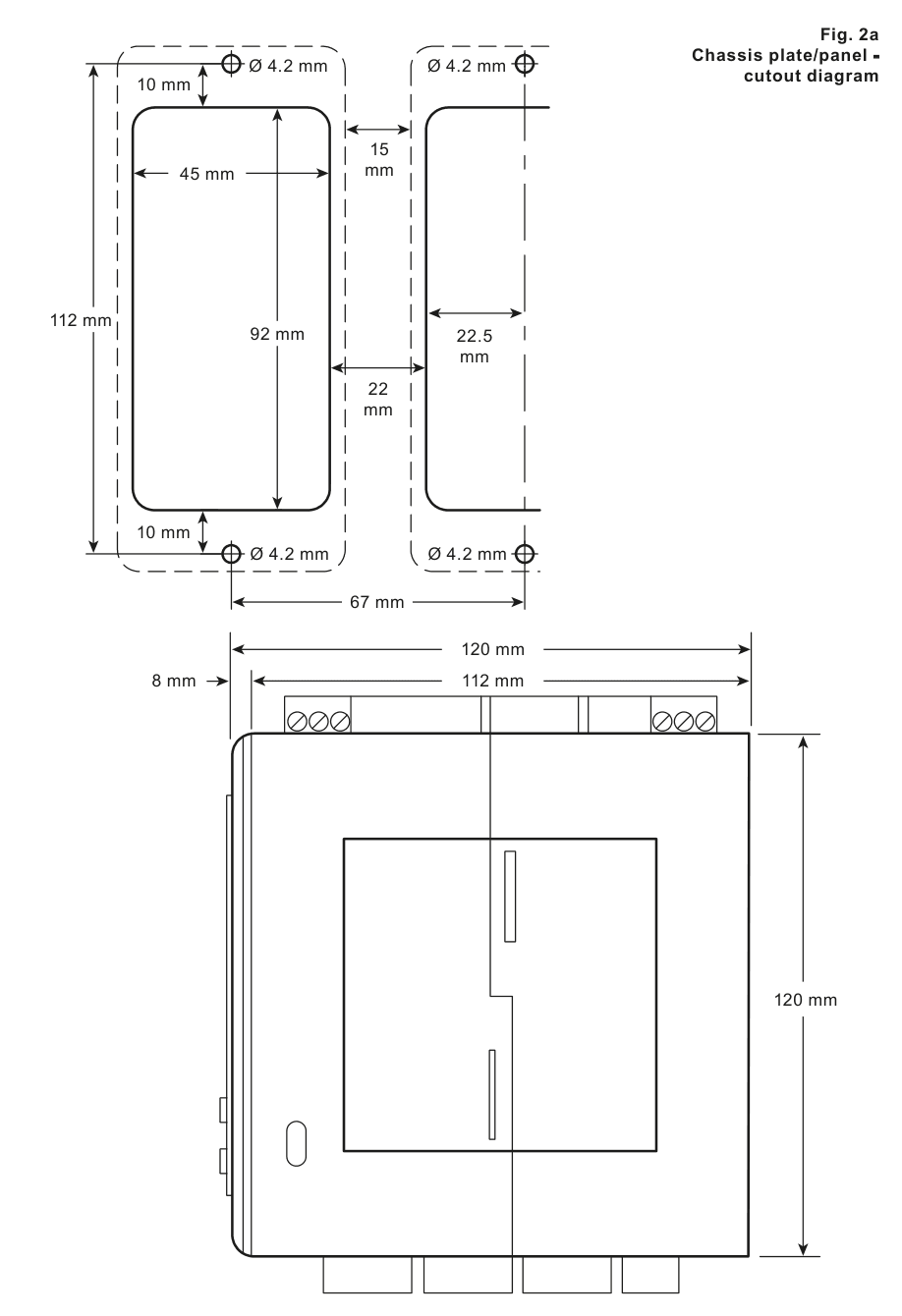
| Panel cut-out | 45 mm x 92 mm. |
| Fixing holes | Four holes, 4.2 mm diameter, in the positions shown in the controlled drawing. |
| Other drawing dimensions | The drawing also labels 112 mm, 67 mm, 22.5 mm, 22 mm, 10 mm and 8 mm reference dimensions. Confirm the full drawing before drilling or cutting. |
Standards and safety references
The exact-model installation guide references EN 12953, EN 12953-9, EN 12952, EN 12952-11 and EN 50156 for boiler and electrical installation requirements, EN 61326-1 for EMC, EN 61010-1, UL61010-1 and CAN/CSA C22.2 No. 61010-1 for electrical safety, EN 60825-12 for optical safety information and VdTUV requirements for water-level control and limiting devices. BS 7671 and the applicable national electrical code also apply where relevant. Confirm the applicable edition, approval route and local legal requirements for the actual installation.
The LC3050/LP30 low-level alarm system functional-safety assessment states SIL2 for a 1oo1 architecture and SIL3 for a 1oo2 architecture under its documented conditions. The complete installation information, proof-test interval, replacement-life assumptions and external safety circuitry remain part of that assessment.
1. Safety information
Safe operation is guaranteed only when the product is correctly installed, commissioned, used and maintained by qualified personnel in accordance with these instructions. General installation and safety requirements for plant construction, tools and protective equipment also apply. Follow the applicable IEE, EN 12953, EN 12952, EN 50156, EN 60364, local and national requirements.
Warning: this product operates with hazardous voltages. Incorrect use as a limiter, failure to follow the installation instructions, modification or unauthorised repair can cause injury, death, property damage or invalidation of the approval. Keep these instructions near the installation.
Functional-safety and boiler requirements
LC3050 with the LP30 low-level probe is assessed as a safety accessory in the documented low-level alarm system under IEC 61508-1:2010 and IEC 61508-2:2010. The stated assessment gives SIL2 in a 1oo1 architecture and SIL3 in a 1oo2 architecture, subject to the specified installation, proof testing, lifetime, environmental and operating conditions. The installation guide states that most countries require two independent low-water limiting systems on steam boilers. Each probe must be installed in its own protection tube or chamber with adequate clearance, connected to an independent controller, and wired so that a low alarm isolates the boiler heat supply. A high-water alarm may be part of the control system or a separate system; install an independent high alarm where required by the safety assessment or local rules.
The probe and controller are only part of the safety system. Additional wiring, relays, alarm lamps or bells, burner isolation and other actuators are needed to complete the safety function. Use a suitable water-treatment regime, and consult the approval authority, boiler inspection body, boiler manufacturer and a competent water-treatment company.
General precautions
- Use trained and competent personnel, a safe access platform, suitable lighting and appropriate protective clothing.
- Consider hazardous liquids, gases, hot surfaces, chemicals, dust, moving machinery, fire and electrical interference before work starts.
- Isolate pressure and vent it safely. Do not assume a system is depressurised because a gauge reads zero.
- Allow equipment to cool after isolation to avoid burns. Protect equipment from frost where it can be exposed below freezing.
- Observe electrostatic-discharge precautions when handling electronic assemblies.
- Use only genuine recommended replacement parts. Follow local environmental and disposal requirements.
- Before returning equipment, provide the equipment identity, serial number, fault description and purchase information required by the return procedure.
2. User instructions and delivery information
2.1 General description
The LC3050 is a special-design electronic water-level limiter for conductive liquids. It is suitable for high or low level limiting and alarm duties in steam and hot water boilers. The controller uses an LP30 low-level or LP31 high-level self-monitoring probe. The available supply settings are 110-120 Vac and 220-240 Vac; select the corresponding wiring arrangement before connecting the mains.
2.2 Cyclic self-testing
An automatic cyclic test simulates a probe fault every few seconds and checks the probe, probe cable and controller. Open-circuit and short-circuit conditions in the probe cable are detected. A detected fault activates the alarm response and, in the documented boiler circuit, shuts down the burner. The green LED is lit at normal level and briefly extinguishes during the cyclic test. A red LED indicates an alarm or fault. The front-panel AL button provides a full manual test, and an optional external test button can be wired into the system.
2.3 Delivery and storage
Each package is factory tested, calibrated and inspected. Check the carton for damage on receipt and report visible damage to the carrier and Spirax Sarco. The standard delivery contents are one LC3050 controller, this installation guide, one front bezel, one foam gasket, two fibre washers, two M4 x 20 panel-head screws, one front-panel configuration label and one ENC2 DIN-rail clip. Confirm all parts before installation.
Store the product between 0 °C (32 °F) and 65 °C (149 °F), and between 10% and 90% relative humidity, non-condensing. Before installing or connecting power, ensure there is no condensation inside the unit.
3. System overview
The standard low-level arrangement consists of the LC3050 controller and LP30 low-level probe. A high-level arrangement can use the LP31 probe. If a low or high level, or a system failure, is detected, the red LED illuminates and the dual alarm relays de-energise. The associated alarm circuit can sound an alarm and interrupt the boiler burner circuit. The final circuit must be designed and verified for the actual plant.
LC3050 compares the resistance from the probe through the water to the boiler or vessel shell. When the water level changes the resistance beyond the set limit, a timer applies the preset delay before the internal relay changes state. A compensation tip on the probe helps compensate for leakage to earth caused by scale, dirt or internal moisture. The controller can communicate by infrared with an adjacent compatible controller in the same enclosure; it is an IR slave only.
The controller contains separate safety and communications/monitoring electronics. The communication and monitoring section does not replace the safety relay circuit or the required manual proof test.
4. Mechanical installation
Read the safety information before installing. Protect the rear of the product from pollutants entering the unit. Install it in a suitable industrial control panel or fireproof enclosure that provides impact and environmental protection. A minimum of IP54 to EN 60529, or Type 3, 3S, 4, 4X, 6, 6P or 13 to UL50/NEMA 250, is required. Use a higher degree of protection in conductive dust or wet conditions.
- Install the product in the vertical orientation only.
- Keep the infrared beam between adjacent products unobstructed.
- Ensure the red and green indicators remain visible to the operator.
- Keep the boiler control-panel or enclosure doors closed during normal use.
- Do not install outdoors without additional weather protection.
- Do not open the sealed product; it has no replaceable parts or internal switches.
4.1 DIN-rail mounting
Fit the supplied clip to one of the rear mounting-hole positions and secure it with the two supplied screws. Engage the spring clip fully with the 35 mm DIN rail. Use only the screws supplied with the product.
4.2 Chassis-plate mounting
Drill the chassis plate using the dimensions in the drawing. Fit the controller to the plate and secure it with two screws, nuts and washers through the case slots. Do not drill the product case or use self-tapping screws.
4.3 Panel mounting
For panel mounting, use the integral M4 x 0.7 threaded inserts, the supplied M4 screws, fibre washers, gasket and bezel. If the bezel is used, the minimum panel thickness is 1 mm. Do not use screws longer than 25 mm because of the risk of electric shock. Cut the panel to the dimensions shown below, drill the fixing holes, fit the gasket and secure the unit from the rear. Tighten the M4 screws to 1 - 1.2 N m. Allow at least 15 mm between adjacent units for cooling.
5. Electrical installation
Warning: isolate the mains supply before touching terminals. Mains and relay terminals may carry hazardous voltage. Use only the supplied or approved replacement connectors, and ensure the unit is free from condensation before connecting power.
5.1 General wiring notes
- Maintenance personnel must be qualified to work on hazardous live equipment.
- The building electrical installation provides primary isolation and overcurrent protection. Include 100 mA protection in all phase conductors. If both supply wires are protected, operation of one protective device must also disconnect the other.
- Fit a 3 A quick-blow protective device to the relay in the burner circuit.
- Relay contacts must be supplied from the same phase as the mains supply.
- Install wiring to IEC 60364, EN 50156, BS 6739 or the applicable local equivalent. For NEC Class 1 wiring, use cable rated above 75 °C where the local installation requires it.
- Connect cable screens as shown in the diagrams to meet EMC requirements. Keep hazardous live circuits separated from safety extra-low-voltage circuits and maintain double or reinforced insulation.
- Secure external wires mechanically so a loose wire cannot contact an accessible part. Provide a nearby, clearly marked disconnecting device that disconnects all phase conductors and does not interrupt protective earth.
5.2 Mains wiring
For the 220/240 Vac setting, connect live to terminal T1 (L1) and neutral to terminal T3 or T4. For the 110/120 Vac setting, connect live to terminal T2 and neutral to terminal T3 or T4. Terminals T3 and T4 are internally linked. Fit fuses in all live conductors. The relays and switches in the wiring diagrams are shown in the power-off position.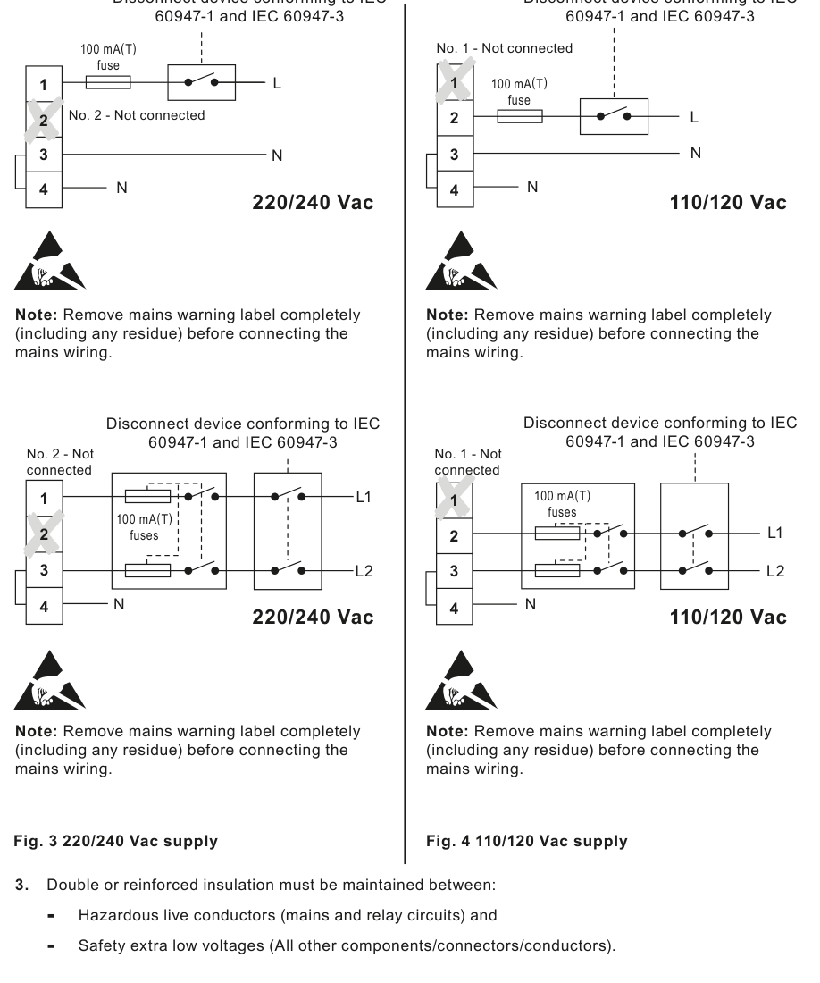
5.3 Probe wiring
The maximum cable length for LP30 and LP31 probes is 50 m. UL probe versions use four colour-coded 18 AWG flying leads and require a suitable metal terminal box and flexible metal conduit for environmental protection. Follow the relevant probe installation instructions for the probe, extension and protection tube.
5.4 Signal wiring and earth
Connect the cable screen to earth at one end only to prevent an earth-current loop. The E terminal is a functional earth, not a protective earth; connect it to a clean local earth in the panel so the controller can drain electrical interference and meet EMC requirements. The probe body-to-pipework or boiler-shell resistance must be less than 1 ohm. Follow the terminal diagram for the comparator tip, alarm tip, internal link and optional normally open external test button.
6. Commissioning and proof testing
During normal boiler operation with the water level normal, the green LED is lit and the boiler-panel indicators show normal level. The green LED briefly extinguishes during automatic cyclic testing.
6.1 Manual AL test
- With the water level normal, press and hold the AL button for approximately 5-6 seconds until the green LED extinguishes and the red alarm LED illuminates. The boiler-panel indicators, alarm lamps or bells and burner isolation response should indicate an alarm.
- Release the button. After a short delay, the green LED should illuminate and the red LED should extinguish. Reset any external boiler lockout if required.
- If an external test button is connected, repeat the same test sequence with that button.
- Use the boiler controls to lower the level below the low alarm point, or raise it above the high alarm point where a high-level arrangement is installed. Confirm the red LED, alarm circuit and burner or controlled-load response.
- Restore the normal level. Confirm that the relays re-energise only according to the approved circuit and that the burner can restart after any required reset.
The manual test is required because the automatic cyclic test does not test the complete downstream shutdown circuit. Perform proof tests at the interval required by local regulations and the safety assessment, normally at least as frequently as the documented system requires.
7. Communications
Compatible products can communicate through the infrared link between adjacent controllers. The link passes LC3050 parameters to a compatible product fitted with RS485. LC3050 is always an infrared slave and requires no local setup or adjustment for this role. Do not cover or obstruct the infrared beam. Keep adjacent products within the documented 10 cm range and 15-degree working angle. The appendix identifies the identity value as IR0 and records a temporary master-slave communication offset of +32768 when applicable.
8. Maintenance
The sealed controller has no routine internal servicing or user-replaceable parts. During maintenance, protect the rear of the product from environmental pollutants or carry out the work in a clean, dry environment. Boiler water-level controls and alarms still require regular inspection and testing. The guide refers to Health and Safety Executive Guidance Note PM5 for general guidance where applicable.
8.1 Low-level alarm proof check
Use the boiler controls to lower the water level. When the level falls below the probe tip, the green LED should extinguish, the red LED should illuminate, the alarm circuit should operate and the burner should be turned off. Restore the level and confirm the normal indication and relay recovery. Check the low-level alarm point at commissioning, after replacing the probe and at the interval required by local legislation, usually annually.
8.2 Probe clearance and cleaning
The probe tip must not touch the boiler, protection tube or other metalwork. The documented clearance requirement is at least 14 mm. If the cyclic or manual test detects a probe tip short to earth, follow the probe clearance test procedure. Clean and inspect the LP30 annually, paying particular attention to threaded contact surfaces and deposits of insulating scale or oxide; more frequent cleaning may be needed for poor boiler-water quality.
9. Fault finding
Warning: hazardous voltages are present. Isolate the mains before touching terminals. Only suitably qualified personnel should fault-find, and the rear of the product must remain protected from contamination.
| Symptom | Checks and action |
|---|---|
| No LEDs lit | Switch off the mains. Check wiring, the selected live terminal, external fuses and the supply range. Re-energise only after the checks. If the condition remains, return the product for examination and consider whether mains surges require a local AC line protector. |
| Red LED remains on for LP30 low alarm | The source fault table identifies this as red LED2. Check for an open probe-cable connection to the low alarm tip, a comparator tip short to earth, an open earth, crossed probe wires or a short between the low alarm tip and comparator tip. |
| Red LED remains on for LP31 high alarm | The source fault table identifies this as red LED3. Check for a shorted high alarm-tip cable, an open probe-terminal connection, an open earth or crossed probe wires. |
| Red and green LEDs remain on | Check for a low alarm-tip short to earth, crossed probe wires or an open comparator tip in the LP30 arrangement; for LP31, check an open high alarm-tip circuit or crossed probe wires. |
| Green LED flashes at start-up and red LED lights for about 12 seconds | This can be the normal start-up self-check. The controller has simulated a fault and is continuing its automatic cyclic check if the green LED then flashes approximately every four seconds. |
| High or low water alarm | Check the actual boiler level immediately. If the level is in the alarm area, take action to normalise it. If the level is normal, isolate the boiler and investigate the fault. |
| Controller internal thermal fuse suspected | Check that the supply is below 264 Vac or 132 Vac as applicable and that the panel ambient temperature is below 55 °C. Check the probe supply voltage as specified in the guide. A failed internal fuse requires product replacement or approved service. |
10. Technical information and return procedure
For technical assistance, contact the local Spirax Sarco representative. When returning equipment, pack it safely and provide the name, company, address, telephone number, order or invoice information, return address, equipment description and serial number, fault description and warranty details where applicable.
11. Appendix - data registers
| Register | Parameter or meaning |
|---|---|
| 0 | Identity. When the device is an IR slave and a temporary master-slave communication error occurs, an offset of +32768 is added to the identification value stored in the master database. |
| 1 | Alarm status: 01 = normal; 00 = alarm. |
| 2-6 | No parameter assigned in the documented register table. |
| 7-9 | No parameter assigned in the documented register table. |
The functional-safety assessment records an SFF of 99.1% for the stated low-water detection analysis. Its assumptions include a one-year proof-test interval, an eight-hour mean time to repair and replacement of electrolytic capacitors every eight years. The applicable assessment conditions must be reviewed for the actual system.
The register data is a 16-bit integer format with the most significant byte transmitted first.