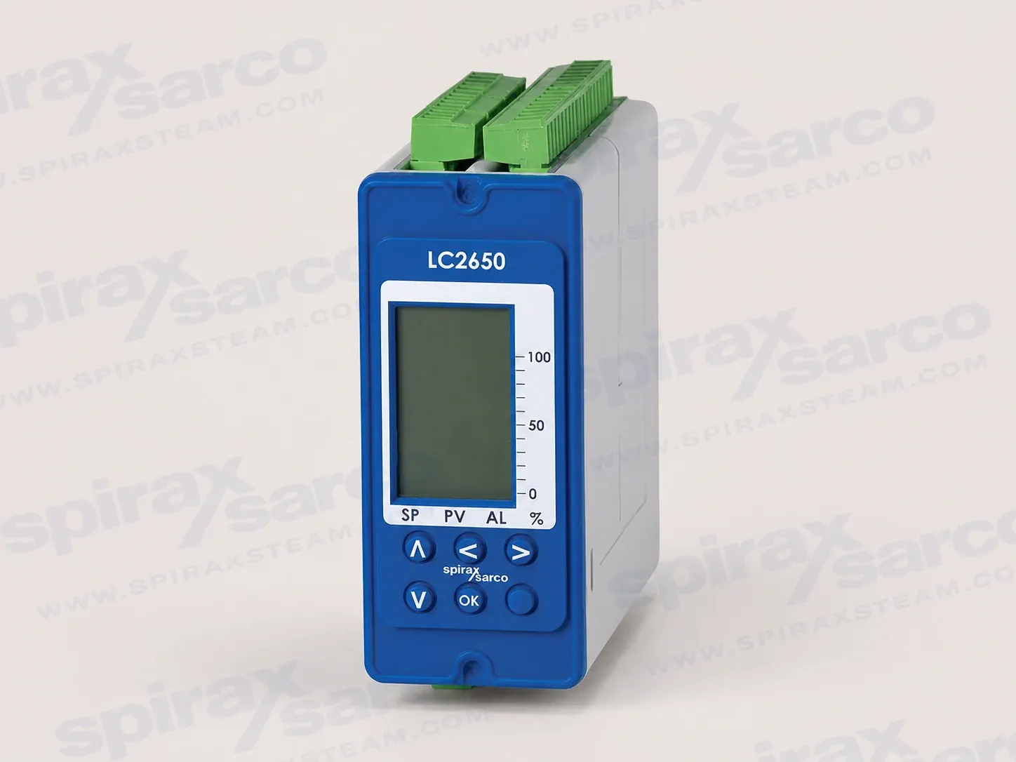
LC2650 Level Controller

LC2650

LC2650 Level Controller

LC2650 is a configurable level controller for conductive liquids in boilers, tanks and vessels, with two high/low alarm channels, on/off or modulating control, and 1-6 V or 4-20 mA level inputs.

LC2650 conductive-liquid level controller

The Spirax Sarco LC2650 is a configurable level controller for conductive liquids in boilers, tanks and vessels. It compares the measured level with a user-defined set point and uses the selected control strategy to operate a pump, solenoid valve or modulating valve. Two independent alarm channels can each be configured for high or low level conditions, giving the control system a practical way to manage normal level control and alarm functions from one graphics-display instrument.

The controller is intended for applications where the level signal, the control output and the alarm response need to be commissioned together. The LC2650 accepts either a 1-6 V signal from the documented capacitance-probe arrangement or a 4-20 mA signal from a compatible transmitter. When the LP20, PA20 or PA420 arrangement is used, the source documents specify a minimum conductivity of 5 uS/cm or 5 ppm. The complete probe, preamplifier, transmitter and boiler installation must be checked separately for compatibility; the controller does not replace the probe instructions or the site's independent safety systems.

Control for changing boiler and vessel conditions

For on/off duty, the Spirax Sarco LC2650 can switch a pump or solenoid valve and provide two alarm outputs together with an isolated level retransmission signal. For modulating duty, it can drive a motorised valve through a valve motor drive arrangement or provide a 4-20 mA control signal for a positioner. The same controller can be configured for two-element control, using a steam-meter signal to compensate for the apparent level rise that accompanies changing steam demand. Where feedwater pressure or flow varies significantly, three-element control adds a water-flow signal to the level and steam inputs.

These operating modes are useful when a boiler needs more than a simple fixed switching point. A steam-meter signal can prevent the feedwater response from following an apparent swell in the gauge-glass level, while a water-meter signal can compensate for changes in feedwater flow. The control arrangement still has to be selected and commissioned for the actual boiler, valve, pump and measurement points. The LC2650 provides the controller functions; it does not determine the correct boiler set point, alarm level, valve sizing or water-treatment regime.

Graphics display, trend view and protected setup

The front panel combines an LCD graphics display with a five-button keypad. In run mode, the display can show the process variable, set point and alarm information through bar graphs, while a trend screen records level variation over a selectable time base. The information line can show units, alarm state and pump or valve status. This gives operators a direct view of the level signal and the control state without relying on a separate display for everyday checks.

A test menu supports commissioning and fault-finding by allowing inputs to be measured and outputs to be set from the front panel. A selectable filter can increase damping where turbulence causes unwanted signal variation. Commissioning parameters are protected by a passcode, helping to reduce inadvertent changes to alarm type, alarm level, control mode, set point, control band and communication settings. The setup process must still be performed by competent personnel who understand the complete boiler or vessel control scheme.

Integration with control systems

The LC2650 provides isolated 0-20 mA or 4-20 mA retransmission according to the selected configuration, relay contacts for the two alarm channels and RS485 communication using Modbus RTU. The RS485 interface supports two-wire half-duplex or four-wire full-duplex arrangements. An infrared link can pass parameters between adjacent compatible controllers; the LC2650 can be assigned as an infrared master or slave. These interfaces allow level, alarm and selected controller parameters to be shared with a local control architecture, while the wiring, termination, shielding and grounding must follow the installation guide and the requirements of the actual network.

In a Spirax Sarco LC2650 installation, the signal layout separates the level input, optional steam- and water-meter inputs, feedback potentiometer, retransmission output, valve motor drive terminals and communication terminals. Screened cable and a clean local functional earth are important to the documented EMC arrangement. Transducer cable length is limited to 100 m, and the RS485 cable length is limited to 1,200 m under the stated cable conditions. These limits are design inputs for the installation rather than promises that every site will achieve the same signal quality.

Mounting and environmental boundaries

The controller can be installed on a 35 mm DIN rail, a chassis plate or in a panel cutout. It must be mounted vertically, with the display readable by the operator and the infrared beam unobstructed where adjacent units communicate. The product is sealed and has no user-replaceable internal parts or switches. It is intended for indoor use, with an ambient range of 0 to 55 deg C and a maximum altitude of 2,000 m. The installation enclosure must provide at least IP54 protection or the applicable listed UL50/NEMA type for the environment; the front-panel IP65 and NEMA Type 4 statements in the source documents apply only within their stated approval scope.

The technical information drawing identifies an approximate front width of 52 mm, a front height of 140 mm and a 120 mm side dimension. The installation drawing gives the panel cutout, mounting-hole positions and minimum spacing between adjacent units. These drawings should be used when designing a panel, and the complete installation must also provide suitable protection from condensation, conductive dust, water, heat, vibration, shock and electrical interference.

Selection checks before ordering

Before specifying the Spirax Sarco LC2650 Level Controller, confirm the liquid is within the intended conductive range and choose the probe or transmitter arrangement that provides the required signal over the full level range. Confirm whether the application needs pump or solenoid on/off operation, valve motor drive, or a 4-20 mA positioner signal. For two- or three-element control, confirm the available steam- and water-meter signals, their scaling and the required control response. Define each alarm as high or low, decide whether the alarm must latch, and verify how each relay will isolate or signal the relevant plant equipment.

Panel design should account for the vertical mounting requirement, the 45 mm by 92 mm panel cutout shown in the installation guide, the 15 mm minimum gap between units for cooling, access to the supplied terminal blocks and the required disconnect and overcurrent protection. Check cable type, screen termination, cable length and functional-earth connections before wiring. The controller accepts hazardous mains and relay circuits as well as low-voltage signal circuits, so the required insulation, fusing and separation must be built into the panel.

Safety-system boundary

For steam-boiler use, the LC2650 and its level probe are only components within the complete control and limiting system. The installation guide requires independent low-water limiting arrangements, separate protection tubes or chambers for level probes, independent controllers where required and regular functional testing of boiler water level controls and alarms. A suitable water-treatment regime is also necessary for safe, correct and continuous operation. Local regulations, approval authorities, the boiler inspection body and the boiler manufacturer remain the controlling references for the finished system.

For projects specifying the Spirax Sarco LC2650, the key decision is not simply whether the display fits the panel. The input technology, control mode, alarm action, measurement range, boiler dynamics, communications, enclosure and safety circuit must all agree. The exact technical tables, wiring diagrams and installation instructions that follow provide the values and procedures needed to take that selection into a controlled design review.
Product and application limits

LC2650 is a level controller for conductive liquids. It can provide on/off or modulating control for a boiler, tank or vessel and has two alarm channels that can each be configured as a high or low alarm.

ItemVerified information
Input mediumConductive liquid level, using the documented probe or transmitter arrangements.
Minimum conductivity5 µS/cm or 5 ppm when used with LP20, PA20 or PA420 as stated in the installation guide.
Documented operating-limit note32 bar at 239 °C, stated in the exact-model technical overview. This is a product/system selection note, not an unconditional pressure rating for a vessel, boiler or controller enclosure.
Control modesOn/off, modulating, two-element or three-element control, subject to the selected inputs and output arrangement.
Mounting35 mm DIN rail, chassis plate or panel mounting. The unit must be installed vertically.

Front panel and display

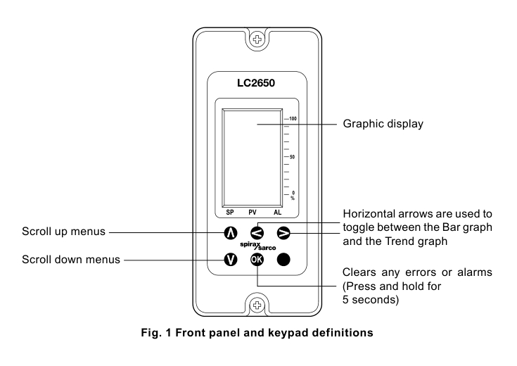
The front panel has an LCD graphics display and a five-button keypad. The run display provides four large digits, an information line and three bar graphs for the process variable, set point and alarms. A trend graph can show level variation over a selected time base.

LC2650 front panel with LCD graphics display, five-button keypad and bar graph controls
Figure 1. LC2650 front panel and keypad definitions, adapted from IM-P402-128 EMM Issue 7, page 9.

Power supply and environment

ParameterValue
Mains voltage range110 V to 240 Vac at 50/60 Hz
Power consumption7.5 W maximum
UseIndoor use only
Maximum altitude2,000 m (6,562 ft) above sea level
Ambient temperature0 to 55 °C (32 to 131 °F)
Relative humidity80% up to 31 °C (88 °F), decreasing linearly to 50% at 40 °C (104 °F)
Overvoltage categoryIII
Pollution degree2 as supplied; 3 when installed in an enclosure with at least IP54 or the applicable UL50/NEMA type.
Installation enclosureMinimum IP54 to EN 60529 or Type 3, 3S, 4, 4X, 6, 6P or 13 to UL50/NEMA 250, as applicable to the installation.
Front-panel protectionIP65 verified by TRAC Global; NEMA Type 4 hose-down only under UL approval. These ratings apply to the front panel within the stated scope.
Panel screw torque1.0 to 1.2 N m

Construction, terminals and cables

ItemValue
EnclosurePolycarbonate
Front panelSilicone rubber, 60 Shore
Mains and signal terminalsRising-clamp plug-in terminal blocks with screwed connectors
Terminal cable size0.2 mm2 (24 AWG) to 2.5 mm2 (14 AWG)
Stripping length5 to 6 mm
Probe, feedback, steam-meter and water-meter cableHigh-temperature, screened; 3 cores for LP20/PA20 or 2 cores for the LP20/PA420 4-20 mA transducer; 1 to 1.5 mm2 (18 to 16 AWG); maximum 100 m.
4-20 mA output cableScreened twisted pair, one pair, 0.23 to 1 mm2 (24 to 18 AWG), maximum 100 m.
RS485 communication cableScreened twisted pair, 2 or 3 pairs, 0.23 mm2 (24 AWG), maximum 1,200 m. Category 5/5E screened, foil or shielded cable may be used up to 600 m.

Safety note: Use only the connectors supplied by Spirax Sarco or approved replacement connectors. Different connectors may compromise safety and approvals.

Input technical data

InputParameterValue
Level voltageMinimum voltage0 Vdc, or 1 V with the OUTRANGE function selected
Maximum voltage6 Vdc; absolute maximum 7 Vdc
Input impedance28 kΩ
Accuracy5% FSD over the operating range
Repeatability2.5% FSD over the operating range
Resolution14 bit, approximately 0.15 mV
Sample time260 Hz
4-20 mAMinimum / maximum current0 mA / 22 mA
Input impedance110 Ω
Accuracy5% FSD over the operating range
Repeatability2.5% FSD over the operating range
Resolution14 bit, approximately 1 µA
Sample time260 Hz
Out-of-range alarmVoltage: low alarm below 0.2 Vdc, recovery above 1 Vdc; high alarm above 6.5 Vdc, recovery below 6 Vdc. Current: low alarm below 2.5 mA, recovery above 4 mA; high alarm above 21 mA, recovery below 20 mA.

Output technical data

OutputParameterValue
24 Vdc supplyNominal voltage24 Vdc
Maximum current25 mA
0/4-20 mA outputMinimum / maximum current0 mA / 20 mA
Open-circuit voltage19 Vdc maximum
Resolution1% FSD
Maximum output load500 Ω
Isolation / output rate100 V / 10 outputs per second
Relay outputsContacts2 x single-pole changeover relays (SPCO)
Maximum voltage250 Vac
Resistive load3 A at 250 Vac
Inductive load1 A at 250 Vac
AC motor load1/4 HP (2.9 A) at 250 Vac; 1/10 HP (3 A) at 120 Vac
Pilot dutyC300 (2.5 A), control circuits/coils
Electrical / mechanical life3 x 105 operations or greater depending on load / 30 x 106 operations

Communications

InterfaceParameterValue
RS485Physical layer4-wire full duplex or 2-wire half duplex
ProtocolModbus RTU format
Isolation60 Vac/dc
Receiver loadUp to 256 devices, subject to the stated unit-load condition
Output rateUp to 10 frames per second
InfraredPhysical layerIrDA
Baud rate38,400
Range / working angle10 cm / 15 degrees
Eye safetyDoes not exceed accessible emission limits for Class 1 under the cited source information.

Approximate dimensions and mass

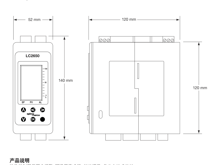
The technical information sheet shows approximate dimensions of 52 mm front width, 140 mm front height and 120 mm side/depth dimension. The approximate mass is 550 g. Use the installation cutout drawing for panel fabrication and allow the specified clearance between adjacent units.

Installation boundary: The product must be installed in a suitable industrial control panel or fireproof enclosure and must not be installed outdoors without additional weather protection.

LC2650 approximate front and side dimensions showing 52 mm, 140 mm and 120 mm dimensions
Figure 2. Approximate LC2650 front and side dimensions from TI-P402-134 AB Issue 6, page 4.

Safety, installation and maintenance note

This technical information does not contain sufficient information for safe installation by itself. The unit operates with hazardous voltages and must be installed, commissioned and maintained by qualified personnel using IM-P402-128 EMM Issue 7 and the applicable local electrical, boiler and approval requirements.

Do not attempt to open the sealed product. Boiler water level controls and alarms require testing and inspection even though the controller itself requires no special preventive servicing. Use the installation guide's wiring, enclosure, fusing, functional-earth, probe and communication instructions for the complete system.

1. Safety information

Safe operation of LC2650 is guaranteed only when it is correctly installed, commissioned, used and maintained by qualified personnel in accordance with this guide. General installation and safety requirements for plant construction, tools and protective equipment also apply.

Intended use and system limits

Check that the product is suitable for the intended fluid and application. Check material suitability, pressure, temperature and their maximum and minimum values. If a product limit is lower than the system limit, or if a malfunction could create dangerous overpressure or overtemperature, provide a suitable protective device.

Determine the correct installation situation. Spirax Sarco products are not intended to withstand external stresses from the connected system; the installer must consider and minimise those stresses.

Competent personnel and working conditions

Provide safe access, a guarded working platform and adequate lighting before detailed work. Assess hazardous liquids or gases, explosion risk, lack of oxygen, hot surfaces, fire, noise and moving machinery around the installation. All work must be carried out or supervised by a suitably competent person, and operating personnel must be trained in the correct use of the product.

Steam-boiler level control

Install two independent low-water limiting systems on steam boilers. Install level probes in separate protection tubes or chambers with sufficient clearance between probe tips and earth. Each probe must be connected to an independent controller. Low-level alarm relays must isolate the boiler heat supply as required by the approved system design.

A high-water alarm may be part of the level control or a separate system. Where an independent high-water alarm is required, its relays must isolate both the feedwater supply and boiler heat supply. Boiler water limiters require regular functional testing.

Complete system and water treatment

The level probe and LC2650 are only part of the complete control system. Additional wiring, relays, alarm indicators and other circuitry are required. Use a suitable water-treatment regime for continuous safe and correct operation, and consult the relevant authorities and a competent water-treatment company.

Electrical and EMC precautions

All wiring materials and methods must comply with applicable EN and IEC standards. The guide cites IEE Regulations, BS 7671, EN 12953, EN 12952 and EN 50156, together with local requirements. Static precautions must be observed at all times. Electrical noise, nearby radio transmitters and mobile radios can cause interference; consider suitable AC power-line protection where mains noise is likely.

Pressure, temperature and access

Isolate and safely vent pressure to atmosphere before work. Consider double isolation, locking or labelling closed valves, and never assume that a system is depressurised because a gauge reads zero. Allow temperature to normalise after isolation to avoid burns. Provide suitable personal protection for chemicals, temperature, radiation, noise, falling objects and eye or face hazards.

Handling, freezing and disposal

Assess manual-handling risks and use a suitable lifting or handling method. Protect the product from freezing where necessary. On disposal, follow local and national requirements. The product is recyclable when handled with due care unless otherwise stated.

Symbols and returns

Follow the document symbols for double or reinforced insulation, functional and safety earth, electric shock, general danger, isolated current circuits and ESD-sensitive circuits. When returning equipment, provide written information about contamination residues or mechanical damage that could create a health, safety or environmental risk.

2. User instructions and delivery information

2.1 Receipt and storage

Inspect the carton at delivery and record visible damage on the carrier's delivery slip. Unpack carefully and check for damage or missing items. Notify Spirax Sarco and the carrier promptly if a problem is found.

Before installation, store the product between 0 and 65 °C (32 and 149 °F) and between 10% and 90% relative humidity, non-condensing. Before connecting power, ensure that there is no condensation inside the unit.

2.2 Operator access

An operator instruction should be used in place of the commissioning section where appropriate, so that the commissioning passcode is not disclosed unnecessarily. The alarm reset passcode may be disclosed only when the responsible system owner considers it necessary.

2.3 Front-panel operation

The up and down buttons scroll through menus. The horizontal buttons toggle between the bar graph and trend graph in run mode. The OK button clears errors or alarms when held for five seconds and is also used to enter commissioning mode and confirm a flashing parameter or digit.

The display shows the process variable and control parameters in large digits, an information line for control state and units, and three percentage bar graphs for process variable, set point and alarms. The information line alternates with pump or valve status; if an alarm occurs, the alarm type is shown instead.

3. System overview

3.1 Function

LC2650 compares the level input with the set point and controls the water level of a boiler, tank or vessel by operating a pump, valve or solenoid valve.

ConfigurationDocumented functions
On/off controlPump or solenoid control, two alarm outputs and isolated 0/4-20 mA level retransmission.
Modulating controlValve motor drive or 4-20 mA control signal, two alarm outputs and isolated level retransmission.
Two-element controlModulating control with a steam-meter feedback signal to compensate for changing steam demand.
Three-element controlTwo-element control with an additional water-flow signal to compensate for varying feedwater flow.

3.2 Inputs

  • Level probe or transmitter: 1-6 V or 4-20 mA.
  • Steam meter: 4-20 mA for two-element compensation.
  • Water meter: 4-20 mA for three-element compensation.
  • Feedback potentiometer for a valve motor drive arrangement.

3.3 Outputs and functions

  • Configurable control output for a pump or modulating valve.
  • Two relay outputs for high- or low-level alarms.
  • Isolated 0-20 mA or 4-20 mA retransmission.
  • RS485/Modbus access to selected parameters.
  • Infrared communication between adjacent compatible controllers.

An additional filter can increase damping in turbulent conditions. The test function can measure inputs and set outputs from the front panel. Commissioning parameters are protected by a passcode.

3.4 Typical two- and three-element arrangements

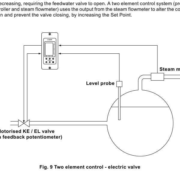
When steam demand changes suddenly, the apparent gauge-glass level can rise even while the mass of water is decreasing. A two-element arrangement uses the steam-meter signal to alter the control action and avoid an inappropriate valve response. A three-element arrangement adds a water-flow meter where feedwater pressure or flow varies considerably. These examples do not replace the boiler manufacturer's control design or commissioning procedure.

LC2650 two-element boiler level control with level probe, steam meter and motorised valve
Figure 1. Two-element control example with a level probe, steam meter and motorised valve, from IM-P402-128 EMM Issue 7, page 20.

4. Mechanical installation

Install the product in a suitable industrial control panel or fireproof enclosure for impact and environmental protection. A minimum of IP54 to EN 60529 or Type 3, 3S, 4, 4X, 6, 6P and 13 to UL50/NEMA 250 is required as applicable. Extra protection is required in conductive dust or wet conditions.

Install the product only in the vertical orientation. Keep the infrared beam between adjacent products clear and ensure that the display can be read easily. Keep the boiler control panel or enclosure doors closed except during installation or maintenance. Do not install outdoors without additional weather protection. The product is sealed and has no replaceable parts or internal switches; do not attempt to open it.

4.1 DIN-rail mounting

  1. Fit the supplied clip to one of the two sets of rear mounting holes to select the height position.
  2. Secure the clip with the two supplied screws.
  3. Engage the spring clip fully with the 35 mm DIN rail.

Warning: Use only the screws supplied with the product.

4.2 Chassis-plate mounting

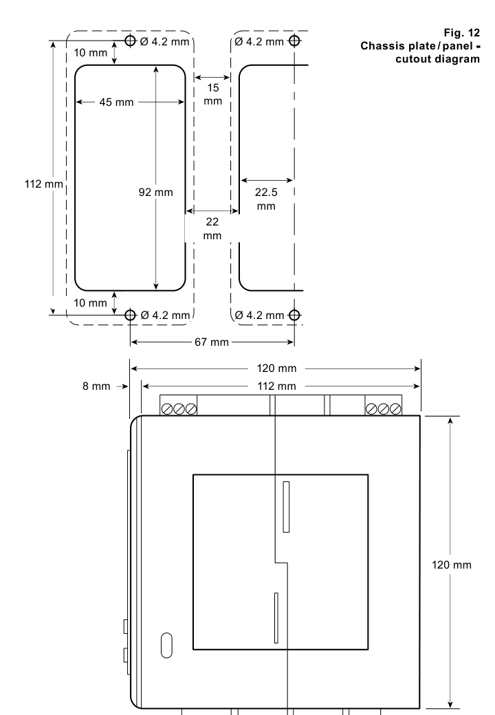
  1. Drill the chassis plate using the dimensions in Figure 12.
  2. Fit the unit to the plate and secure it with two screws, nuts and washers through the top and bottom case slots.

Warning: Do not drill the product case or use self-tapping screws.

LC2650 chassis plate and panel cutout diagram with 45 mm by 92 mm cutout and 4.2 mm mounting holes
Figure 2. Chassis plate and panel cutout drawing. It shows the 45 mm x 92 mm cutout, 4.2 mm mounting holes, 15 mm minimum gap and the 120 mm enclosure dimension.

4.3 Panel cutout mounting

For panel mounting with the bezel, use a panel at least 1 mm thick. The front panel has integral M4 x 0.7 threaded inserts. Use the two supplied M4 x 25 mm screws, fibre washers, gasket and bezel where required. Do not use screws longer than 25 mm because of electric-shock risk.

  1. Cut and drill the panel to the dimensions shown in Figure 12.
  2. Remove the backing from the supplied gasket and apply it to the front face of the product.
  3. Fit the bezel to the outside of the panel when required.
  4. Fit the unit from the rear of the panel and secure it with the supplied screws, washers and bezel.
  5. Tighten the M4 screws to 1.0-1.2 N m.

Cooling and spacing: Provide a minimum 15 mm gap between units. The mounting-hole dimensions are the same for panel and wall mounting.

5. Electrical installation

Warning: Isolate the mains supply before touching wiring terminals. Terminals may carry hazardous voltages. Use only the supplied connectors or approved Spirax Sarco replacements, ensure there is no condensation inside the unit and connect the mains supply correctly.

5.1 General wiring requirements

  1. Installation and maintenance personnel must be qualified to work with hazardous live voltages.
  2. Building wiring provides primary isolation and overcurrent protection. Include 3 A overcurrent protection in all phase conductors; if both supply wires are protected, operation of one must also operate the other.
  3. Fit a 3 A quick-blow overcurrent protection device to each relay circuit.
  4. Relay contacts must be supplied from the same phase as the mains supply.
  5. Install wiring in accordance with IEC 60364, EN 50156, BS 6739 or the applicable local electrical code. Use the specified temperature-rated wire where required by the destination market.
  6. Connect cable screens as shown to meet EMC requirements and maintain double or reinforced insulation on external circuits.
  7. Secure conductors close to the terminal block so a loose wire cannot reach accessible parts.
  8. Provide a nearby, accessible and clearly marked disconnecting device that disconnects all phase conductors, has sufficient breaking capacity, does not interrupt protective earth and meets IEC 60947-1 and IEC 60947-3.

5.2 Mains wiring

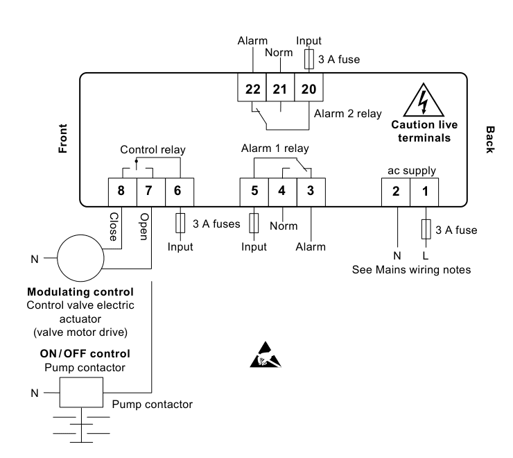
Terminal connections are identified on the terminal plugs. Fit fuses in all live conductors and maintain double or reinforced insulation between hazardous live mains or relay circuits and the safety extra-low-voltage circuits. The wiring diagrams show relays and switches in the power-off position.

LC2650 mains circuit wiring for control relay, alarm relays and 3 A fuses
Figure 3. Mains circuit viewed from the underside. Control, alarm and supply relays are shown in the power-off position.

5.3 Signal wiring and functional earth

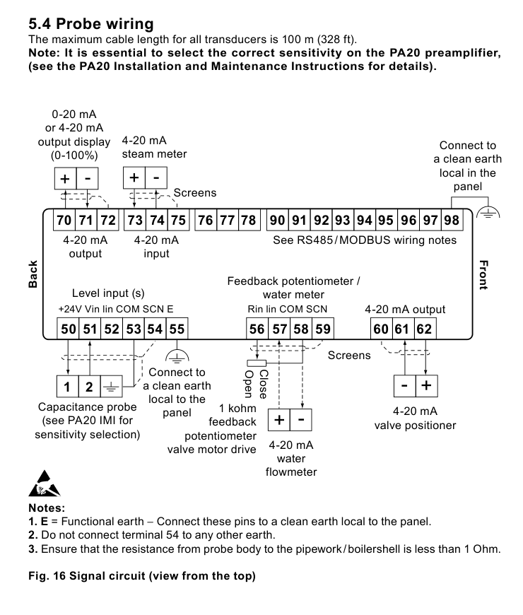
An earth loop can be created if a wire or screen connects two earth points at different potentials. Follow the diagram so that screens are connected to earth at one end only. The earth terminal is a functional earth rather than a protective earth. The product has double insulation, but the functional earth must be connected to a clean local earth so that it can drain electrical interference and meet EMC requirements.

LC2650 signal circuit terminals for capacitance probe, meter inputs, feedback and 4-20 mA output
Figure 4. Signal circuit viewed from the top. The diagram identifies level, steam-meter, water-meter, feedback, retransmission and valve-positioner connections.

5.4 Probe and transmitter wiring

The maximum cable length for all transducers is 100 m. When a capacitance probe and PA20 preamplifier are used, select the correct sensitivity on the preamplifier. Ensure the resistance from the probe body to the pipework or boiler shell is less than 1 ohm. Do not connect terminal 54 to any other earth. Connect the functional-earth terminal to a clean local earth in the panel.

The level output from a PA20 or LP20 capacitance probe can be daisy-chained to more than one instrument when each receiving instrument accepts a 1-6 Vdc signal. Only one instrument needs to provide the nominal 24 V supply for the PA20. For a PA420 or other 4-20 mA transmitter, follow the loop-powered or self-powered arrangement appropriate to that transmitter and connect the screen as shown.

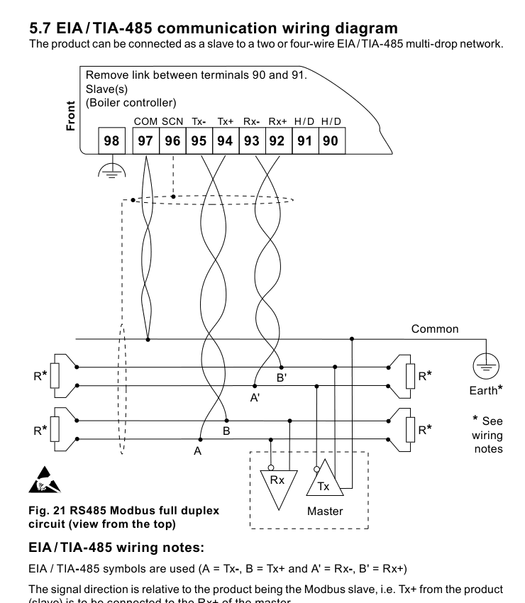
5.5 EIA/TIA-485 and Modbus wiring

The product can connect as a slave to a two- or four-wire EIA/TIA-485 multidrop network. For two-wire half duplex, link terminals 91 and 90. For four-wire full duplex, remove the link. Connect the bus common to protective earth at one point only, normally at or near the master. Consider terminating the two furthest ends of a long bus to match the transmission-line impedance.

LC2650 RS485 Modbus full-duplex circuit showing terminals 90 to 98 and master connection
Figure 5. RS485 Modbus full-duplex circuit viewed from the top. The two-wire link and termination notes continue in the source guide.

6. Commissioning

All commissioning is performed from the front panel. Entering commissioning mode stops normal control: the control relay or 4-20 mA output will shut the valve, or the pump will switch off. Alarm relays continue to operate. Return to the run menu to regain normal control.

If no button is pressed for more than five minutes, the controller returns to run mode and an error occurs. Incomplete commissioning may leave the controller unable to provide correct control. The commissioning passcode must be kept under the control of suitably trained personnel.

6.1 Quick level calibration

  1. Enter commissioning mode by holding OK for five seconds and enter the authorised passcode.
  2. Set the actual level to the top of the gauge glass and store the high-level calibration.
  3. Set the actual level to the bottom of the gauge glass and store the low-level calibration. The water level must remain visible in the gauge glass.
  4. Select the required on/off or proportional control arrangement and complete the relevant valve, pump or retransmission calibration.
  5. Set the set point, control band, alarm type, alarm level, hysteresis, delay and latch behavior for each alarm.
  6. End commissioning and test the complete system, including external alarm circuits and the boiler protection response.

6.2 Main commissioning functions

Menu areaFunction
MODEManual test of the valve or pump output during commissioning.
LEVELSelects 1-6 V or 4-20 mA input, out-of-range alarm and input filtering.
STEAMConfigures the steam-meter input and steam offset for two-element control.
CONTROLSelects on/off or proportional control and the set point, control band, integral action and output action where applicable.
ALARM 1 / ALARM 2Sets each alarm as high or low and configures level, hysteresis, delay and latching.
OUTPUTConfigures retransmission, valve drive and RS485/Modbus communication settings, including address and baud rate.
DISPLAY / TRENDConfigures displayed units and the time base for the level trend graph.
TESTMeasures inputs and manually sets outputs to support commissioning and fault-finding.

Alarm type and level settings must comply with the applicable boiler regulations and the approved system design. A latched alarm remains active until it is cancelled through the authorised commissioning or reset procedure; removing power does not necessarily clear a latched alarm.

7. Communications

7.1 Infrared bus

Compatible controllers can communicate through an infrared bus between adjacent units. Parameters from up to seven products can be passed to a unit fitted with RS485. The LC2650 can be designated as the master or a slave. The controller connected to the RS485 network must be positioned to the left of the slaves on the infrared bus and configured as the infrared master. Do not cover or obstruct the infrared beam.

7.2 RS485 addressing

An address offset is applied according to each unit's position on the infrared bus. The master has an offset of 0, and the units to its right use successive offsets of 100. Read the complete Modbus register summary in the source guide when integrating the controller into a supervisory system.

8. Maintenance

Read the safety information before maintenance. No special servicing, preventive maintenance or inspection of the sealed controller is required. During installation or maintenance, protect the rear of the product from environmental pollutants or carry out the work in a dry, clean environment.

Boiler water level controls and level alarms do require testing and inspection. Follow the applicable boiler guidance and the instructions for the complete Spirax Sarco system. Use a cloth dampened with tap water, de-ionised water or isopropyl alcohol for cleaning. Other cleaning materials may damage the product and invalidate the warranty.

9. Fault finding

Warning: Hazardous voltages are present. Only suitably qualified personnel should fault-find the product, and the product must be isolated from the mains supply before wiring terminals are touched. Relay fuses must be replaced by the manufacturer or an accredited service department.

Incorrect wiring is the most common cause of faults during installation and commissioning. Use the test menu to examine the six viewable input channels and to establish whether the controller is receiving the expected signals.

Displayed conditionInitial checks
Display not illuminatingIsolate the mains, check wiring and external fuses, confirm the mains voltage is within specification, then restore power. Consider mains-borne surges or spikes if the symptom remains.
Display flashesIsolate the mains, disconnect signal wires and restore power for a controlled check. Reconnect signal wires one at a time and investigate the external sensor, transducer or module associated with the fault.
Product powers up then switches offCheck continuity and voltage stability of the mains supply, ambient temperature and total power draw. The internal thermal protection can operate when the stated limits are exceeded.
Outrange high or lowMeasure the input and confirm that the voltage or current does not exceed the product's input technical limits. Check sensor wiring, screens, sensitivity and transmitter configuration.
Alarm 1 or Alarm 2Check the boiler operation, alarm setup, water supply system and external alarm/relay circuit. Confirm whether the alarm is configured high or low and whether it is latched.
Latched alarmEnter the authorised commissioning mode and use the correct reset procedure. Clearing the message from the display alone does not necessarily release the alarm relay.

Reference boundary: This installation and maintenance fragment is condensed from IM-P402-128 EMM Issue 7. Preserve the source guide as the controlling document for site-specific safety assessment, wiring, commissioning, Modbus registers and fault-finding decisions.

Installation and maintenance

DocumentReferenceLanguageDownload
LC2650IM-P402-128-ENEnglishDownload

Talk to our technical team

Contact Spirax Sarco for product selection, documentation or replacement guidance.