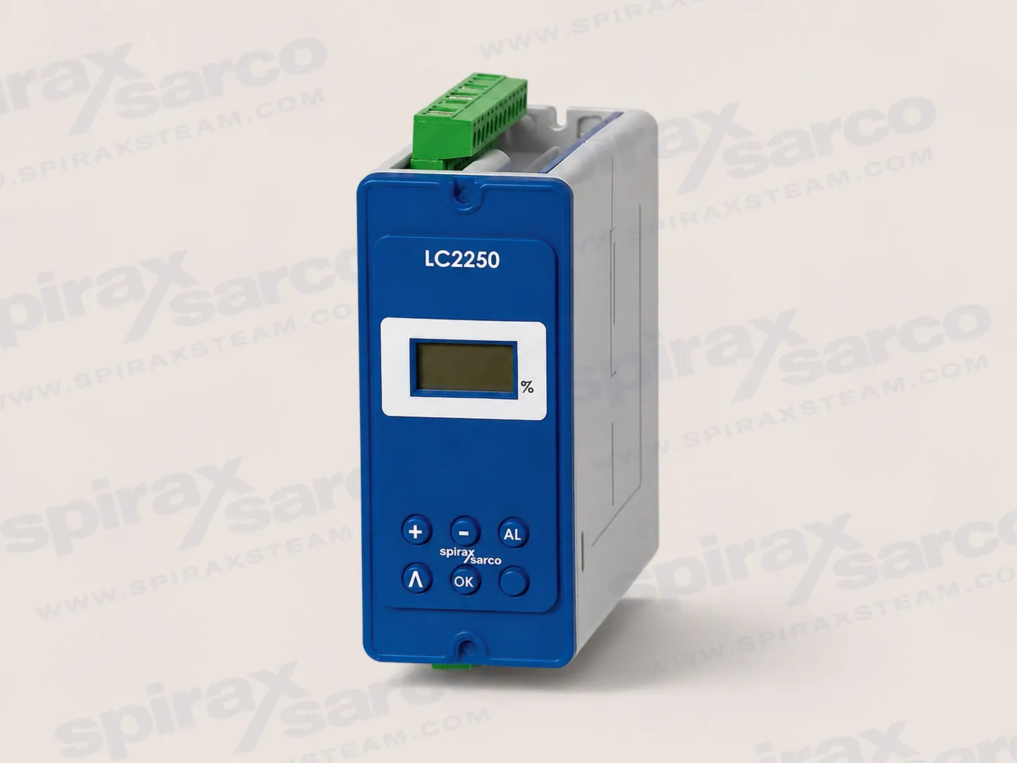
LC2250 is a configurable level controller for conductive liquids in boilers, tanks and vessels. It supports on/off or modulating control, two configurable high/low alarms, and 1-6 V or 4-20 mA level inputs.
LC2250 level controller for conductive liquids
Spirax Sarco LC2250 is a configurable level controller for conductive liquids in boilers, tanks and vessels. It compares the measured level with the operating settings and changes the control output so that a pump, solenoid valve or modulating valve can respond to the process. Two alarm channels can be configured for high- or low-level conditions. This makes the unit suitable for applications that need more flexibility than a fixed switching point while still requiring a clear operator interface and defined alarm behavior.
The controller is intended for use as part of a complete level-control installation. The probe or transmitter, control element, wiring, alarm circuits and boiler or vessel protection arrangements must be selected for the actual plant and local requirements. LC2250 does not by itself replace an independent boiler protection system or the checks required by the boiler manufacturer and applicable regulations.
One controller for on/off and modulating control
LC2250 can be configured for on/off control when the process is managed by a pump or solenoid valve. In this arrangement the controller provides the control output, two alarm outputs and an isolated level retransmission output. A typical use is boiler feedwater control where the switching levels need to be set accurately and the alarm circuits must remain separate from the normal pump command.
For modulating service, LC2250 can operate a control valve through a valve motor drive or accept a 4-20 mA control signal. The output changes as the measured level moves relative to the configured control range, allowing feedwater flow to follow the process rather than waiting for a simple pump-on or pump-off event. The isolated 4-20 mA level output is available when the controller is configured for a valve motor drive system, so the required signal arrangement should be confirmed before ordering.
This two-mode design is useful where one installation may need to support different control strategies during its service life. It also allows the selection of the control element to follow the plant design: a pump or solenoid valve for switching control, or a modulating valve and actuator arrangement for continuous correction.
Signal handling and operator feedback
The level input accepts a 1-6 V signal from a suitable level probe or transmitter, or a 4-20 mA signal from a transmitter. A separate 1 kOhm potentiometer input is provided for valve motor drive applications. The probe must be long enough to sense the complete required level range; a controller cannot compensate for a sensing element that does not cover the actual operating span.
A three-digit LCD and five-button front keypad provide local access to the current level, alarm status, operating mode and commissioning parameters. The display indicates whether a pump is operating in on/off control or whether a valve is opening or closing in proportional control. Moving display segments show whether the level is rising or falling, while a static segment indicates that water input and steam output are in equilibrium. The alarm test function lets a qualified operator check the alarm relays and the external circuits during commissioning or operation.
LC2250 also provides a selectable filter for turbulent conditions. The filter increases damping where rapid level movement would otherwise cause unstable indications or unnecessary switching. It should be chosen during commissioning with the actual vessel, probe and control response in mind; it is not a substitute for correct probe placement, suitable piping or stable water treatment.
Where LC2250 fits
The controller is documented for boiler, tank and vessel level control. In steam boiler service, a Spirax Sarco LC2250 installation is especially useful where steam demand varies and feedwater control needs adjustable switching levels or modulating action. A documented capacitance-sensing arrangement can provide a voltage proportional to water level, while a transmitter-based installation can use the 4-20 mA input for process tanks or other conductive-liquid services.
For tank applications, the required control range, response time, liquid conductivity and alarm philosophy should be established before the instrument is selected. For boiler applications, the level shown in the gauge glass, the feedwater valve or pump behavior, the expected load changes and the required low- and high-level alarm actions must be considered together. The controller's alarm outputs can be used within the plant's approved alarm and shutdown circuits, but the complete safety function depends on the independent wiring, relays, indicators and protective equipment around it.
The unit is an indoor control-panel instrument. It must be installed in a suitable industrial control panel or fireproof enclosure that protects the rear of the unit from impact, moisture, conductive dust and other environmental contamination. The documented minimum enclosure requirement is IP54 or an applicable UL50/NEMA enclosure type. The front panel has an IP65 rating when installed as specified; this does not mean that the complete controller can be mounted outdoors without additional weather protection.
Communication and configuration security
An infrared link allows communication between adjacent compatible boiler-house controllers. LC2250 is defined as a slave unit in this arrangement, so the communication role and the neighboring device must be planned as part of the control system. The infrared path must remain clear and the units must be positioned within the documented working range and angle.
Commissioning is performed from the front panel. The commissioning parameters are protected by a pass code to reduce the risk of an unintended change to a live control system. When commissioning mode is entered, normal control behavior changes while settings are being made, so the work must be carried out by qualified personnel with the plant in a safe condition. Settings are stored in non-volatile memory; the controller has no battery.
Selection checks before ordering
Confirm the measured signal. Specify whether the installation will use a 1-6 V level signal, a 4-20 mA transmitter or the valve motor drive potentiometer input.
Define the control action. Decide whether the output will operate a pump or solenoid valve in on/off service, or a modulating valve through a valve motor drive or 4-20 mA control signal.
Confirm the retransmission requirement. Check whether the receiving equipment needs an isolated 0-20 mA or 4-20 mA signal and whether the selected control configuration supports it.
Set the alarm philosophy. Establish which channels are high or low alarms, whether they must latch, and how each alarm is connected to the approved external warning or shutdown circuit.
Check the sensing range. Ensure the selected probe or transmitter covers the complete operating level and is suitable for the liquid conductivity, temperature and pressure conditions.
Check the enclosure and mounting. Choose DIN rail, chassis or panel mounting and reserve the required panel cut-out, cooling clearance, cable routing and infrared line of sight.
Check the environment and wiring. The controller is for indoor installation, with the stated ambient limits and screened signal wiring. Cable lengths, connectors, overcurrent protection and earthing must follow the installation requirements.
Engineering value in a complete level-control system
LC2250 brings measurement, control, alarm testing and local indication into one panel-mounted instrument. Its value comes from the relationship between those functions: the same measured level can drive a switching output or a modulating response, while the display exposes the operating state and the alarm channels remain available for the plant's protection logic. The filtering option helps adapt the response to a turbulent vessel, and the retransmission output can provide a separated level signal to a recorder, indicator or wider control system when the configuration permits it.
Correct application is more important than selecting a controller in isolation. The final design should verify the process fluid, signal type, complete measurement range, control element, alarm consequences, environmental protection and local electrical rules. With those points confirmed, Spirax Sarco LC2250 provides a practical, configurable level-control platform for conductive-liquid boiler and process applications.
Technical information
Product and application limits
LC2250 is a level controller for conductive liquids. The controller can be configured for a boiler, tank or vessel and can operate a pump, solenoid valve or modulating valve. Two alarm channels can be configured as high or low alarms.
Item
Verified information
Minimum conductivity when used with the documented capacitance arrangement
5 µS/cm or 5 ppm
Documented product operating limit note
32 bar at 239 °C, stated in TI-P402-133 product overview; verify the complete system pressure and temperature design separately.
Control modes
On/off or proportional/modulating control
Mounting options
35 mm DIN rail, chassis plate or panel mounting
Power supply
Parameter
Value
Mains voltage range
110 V to 240 V at 50/60 Hz
Power consumption
7.5 W maximum
Installation category
Category III product
Overvoltage category
III
Pollution degree
2 as supplied; 3 when installed in an enclosure
Environmental and enclosure data
Parameter
Value
Use
Indoor use only
Maximum altitude
2,000 m (6,562 ft) above sea level
Ambient temperature limits
0 - 55 °C (32 - 131°F; 32 to 131 °F)
Relative humidity
80% up to 31 °C (88 °F), decreasing linearly to 50% at 40 °C (104 °F)
Minimum installation enclosure
IP54 to EN 60529, or UL50 / NEMA Type 3, 3S, 4, 4X, 6, 6P or 13 as applicable
Front-panel enclosure rating
NEMA Type 4 hose-down only under UL approval and IP65 verified by TRAC Global; front panel only
Enclosure material
Polycarbonate
Front-panel material
Silicone rubber, 60 Shore
Panel screw torque
1 - 1.2 N m (1.0 to 1.2 N m)
Cable, wire and connector data
Circuit
Requirement
Mains and signal connector
Rising-clamp plug-in terminal blocks with screwed connectors
Terminal cable size
0.2 mm2 (24 AWG) to 2.5 mm2 (14 AWG)
Stripping length
5 - 6 mm (5 to 6 mm)
Level probe and feedback cable
High-temperature, screened, 3-core, 1 to 1.5 mm2 (18 to 16 AWG), maximum 100 m (328 ft); recommended types include Pirelli/Prysmian FP200 and Delta Crompton Firetuf OHLS.
4-20 mA output cable
Screened twisted pair, 0.23 to 1 mm2 (24 to 18 AWG), maximum 100 m (328 ft)
Caution: Use only the connectors supplied with the product. Using different connectors may compromise safety and approvals.
1/4 HP (2.9 A) at 250 Vac; 1/10 HP (3 A) at 120 Vac
Pilot duty load
C300 (2.5 A), control circuits/coils
Electrical life
3 x 10⁵ operations or greater depending on load
Mechanical life
30 x 106 operations
Infrared
Physical layer
IrDA
Baud rate
38,400
Range
10 cm
Working angle
15 degrees
Eye safety
Exempt from EN 60825-12:2007 accessible emission limits for Class 1
Approximate dimensions and mass
Item
Value
Approximate mass
430 g
Approximate dimensions
Refer to the exact-model dimension drawing in the installation information; the technical information sheet identifies 52 mm, 120 mm and 140 mm dimensions.
Approvals and standards stated in the source documents
The English installation guide states compliance with the Electromagnetic Compatibility Directive 2014/30/EU and Low Voltage Directive 2014/35/EU, EN 61010-1:2010, UL61010-1, 3rd Edition, 2012-05, CAN/CSA-C22.2 No. 61010-1, 3rd Edition, 2012-05 and VdTUV requirements for water level control and limiting devices, water 100 (2010). The applicable installation, approval and safety requirements must be confirmed for the destination market and complete system.
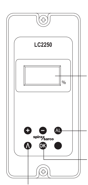
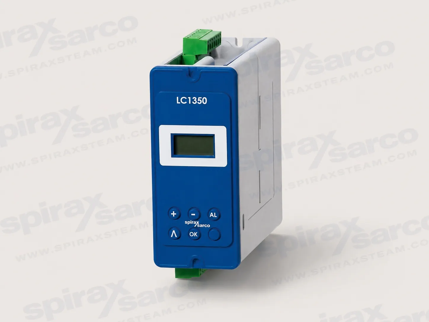
Figure 1. LC2250 front panel and operator controls.
1. Safety information
Safe operation of LC2250 is guaranteed only when it is installed, commissioned, used and maintained by qualified personnel in accordance with this guide. General installation and safety requirements for plant construction, tools and protective equipment also apply.
Intended use and system limits
Check that the product is suitable for the intended fluid and application. Check material suitability, pressure, temperature and their maximum and minimum values. If a product limit is lower than the system limit, or if a malfunction could create dangerous overpressure or overtemperature, provide a suitable protective device.
Determine the correct installation situation and direction of fluid flow. The product is designed as a boiler controller; using it for another purpose, modifying it, repairing it incorrectly or installing it contrary to this guide can cause injury, property damage and loss of marking validity.
Standards and competent personnel
Wiring materials and methods must comply with applicable EN and IEC standards. Observe relevant IEE, BS 7671, EN 12953, EN 12952 and EN 50156 requirements, together with local regulations, approval authority requirements, boiler inspection requirements and the boiler manufacturer's specifications.
All installation, operation and maintenance must be carried out or supervised by a suitably competent person. Follow any permit-to-work system and make sure personnel are trained in the correct use of the product.
Boiler level control and limiting
Steam boilers require two independent low-water limiting systems. Install level probes in separate protection tubes or chambers with sufficient clearance between probe tips and earth. Each probe must be connected to an independent controller, and the low-alarm relays must isolate the boiler heat supply as required by the approved system design.
A high-water alarm may be part of the level control or a separate system. Where an independent high-water alarm is required, its relays must isolate both the feedwater supply and boiler heat supply. All boiler water limiters require regular functional testing. LC2250 and its level probe are only part of the complete safety system; additional wiring, relays, alarm indicators and other circuitry are required.
Electromagnetic compatibility
LC2250 complies with the stated Electromagnetic Compatibility Directive 2014/30/EU requirements and is suitable for Class A industrial environments. Electrical noise, nearby radio transmitters and mobile radios can cause interference. Consider an AC power-line protector where mains noise is likely and keep mobile transmitters away from the product and its wiring.
The product also complies with the stated Low Voltage Directive requirements through EN 61010-1:2010 and is type tested for water level control and limiting devices against the cited VdTÜV water level requirements.
Access, lighting and the surrounding system
Provide safe access and a guarded working platform where needed. Provide adequate lighting for detailed work and suitable lifting equipment where required. Consider flammable or hazardous substances, lack of oxygen, dangerous gases, hot surfaces, fire, noise, moving machinery and other hazards around the installation.
Before isolating valves or electrical supplies, consider the effect on the complete system. Do not render vents, protective devices, controls or alarms ineffective. Operate isolation valves gradually to avoid system shock.
Pressure, temperature and personal protection
Isolate and safely vent pressure to atmosphere before work. Consider double isolation, locking or labelling closed valves, and never assume that a system is depressurised because a gauge reads zero. Allow temperature to normalise after isolation to avoid burns.
Assess the need for protection from chemicals, temperature, radiation, noise, falling objects and eye or face hazards. External surfaces may be hot in normal use. Products that are not self-draining require protection from frost where freezing temperatures are possible.
Handling, disposal and returns
Assess manual-handling risks for the task, the person, the load and the working environment, and use a suitable handling method. On disposal, follow local and national regulations. LC2250 is recyclable and no ecological hazard is anticipated when it is handled correctly unless otherwise stated.
When returning equipment, provide written information about contamination residues or mechanical damage that could create a health, safety or environmental risk, including relevant safety data sheets.
Static precautions
Observe electrostatic discharge precautions at all times. Do not touch or handle ESD-sensitive circuits without suitable protection.
Symbols used in this guide
Double or reinforced insulation protects the equipment throughout.
Functional earth enables correct operation; clean earth and safety earth identify their respective grounding functions.
Electric-shock and general-danger symbols require the accompanying documentation to be followed.
An optically isolated current source or sink identifies the isolated current circuit.
The ESD symbol identifies a circuit that must not be touched without static precautions.
ac identifies alternating current.
2. User instructions and delivery information
2.1 General description
LC2250 is a level controller for conductive liquids with two alarms that can each be configured as high or low alarms. The front panel provides a three-digit LCD and a five-button keypad.
Control indication
Meaning
Alarm
A level alarm is present or has been latched. Press AL to test the alarm relays and external circuits.
Out of range
The level signal is outside its selected input range.
On/off control
A moving segment shows the level rising while pumping in or falling while pumping out. A static segment indicates the pump is off because the level is between the configured switching positions.
Proportional control
A moving segment shows the valve opening or closing. A static segment indicates that water input and steam output are in equilibrium.
2.2 Viewing parameters and errors
In run mode, press the scroll button to view the current level as a percentage of the gauge glass. The value remains visible for two minutes. Press the button again to step through selected parameters; each parameter remains visible for another two minutes unless the button is pressed again.
An error menu is shown after the parameter screens when an error occurs. Holding OK for three seconds can clear a message and re-energise alarm relays; if the cause remains, the message returns. A latched alarm relay remains de-energised until it is cleared with the alarm reset code or commissioning passcode. Multiple errors are displayed in priority order after the preceding error has been cleared.
2.3 Delivery, handling and storage
Each unit is tested, calibrated and inspected before shipment. Inspect each carton on delivery, record visible damage on the carrier's delivery slip, and check the contents after careful unpacking. Notify Spirax Sarco and the carrier immediately if items are damaged or missing.
Before installation, store the product at 0 °C (32°F) to 65 °C (149°F) and 10% to 90% relative humidity, non-condensing. Before connecting power, ensure that there is no condensation inside the unit.
Provide operators with an alternative operating instruction that does not disclose the commissioning passcode. The alarm reset passcode may be disclosed only where the responsible system designer considers this necessary.
3. System overview
3.1 Function
LC2250 can control the level of a boiler, tank or vessel by operating a pump, valve or solenoid valve.
Configuration
Functions
On/off control
Pump or solenoid control, two alarm outputs and an isolated level retransmission output.
Modulating control
Modulating valve control through a valve motor drive or 4-20 mA control signal, two alarm outputs and an isolated level retransmission output. The level output is available with the valve motor drive configuration as stated in the guide.
3.2 Inputs and outputs
Level probe or transmitter input: 1-6 V or 4-20 mA.
1 kOhm potentiometer input for valve motor drive feedback.
Configurable control output for a pump or modulating control valve.
Relay outputs for high- or low-level alarms.
Isolated 4-20 mA level retransmission output, subject to configuration.
3.3 Additional functions
An input filter can increase damping in turbulent conditions. Select the filter during commissioning with care because excessive delay can cause system instability. Commissioning parameters are passcode protected. The unit can communicate with adjacent Spirax Sarco boiler-house controllers through infrared and is always an IR slave.
4. Mechanical installation
Read the safety information before installing LC2250. Install the product in a suitable industrial control panel or fireproof enclosure for impact and environmental protection. The minimum enclosure requirement is IP54 to EN 60529 or the applicable listed UL50/NEMA type; extra protection is required in conductive dust or wet conditions.
Install the unit vertically, keep the infrared beam clear, and position the display where it can be read easily. Keep the boiler control panel or enclosure door closed except during installation or maintenance. Do not install outdoors without additional weather protection.
LC2250 is sealed and has no replaceable parts or internal switches. Do not attempt to open it. During installation and maintenance, protect the rear of the unit from environmental pollutants or carry out the work in a dry, clean environment.
4.1 DIN rail mounting
Fit the clip to one of the two sets of rear mounting holes to select a height position.
Secure the clip with the two screws supplied.
Locate the spring clip fully onto the 35 mm DIN rail.
Warning: Use only the screws supplied with the product.
4.2 Chassis-plate mounting
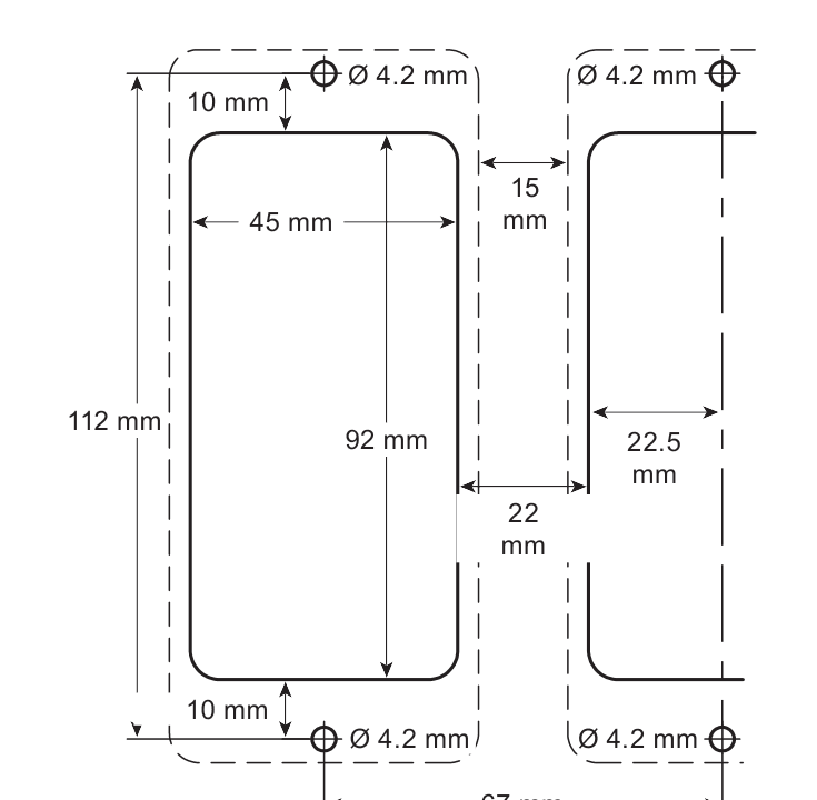
Drill the chassis plate using the dimensions in Figure 2.
Fit the unit to the plate and secure it with two screws, nuts and washers through the slots at the top and bottom of the case.
Warning: Do not drill the product case or use self-tapping screws.
Figure 2. Chassis plate and panel cutout dimensions. The drawing shows the 45 mm by 92 mm cutout, 4.2 mm mounting holes and 15 mm minimum gap between adjacent units. It also marks 10 mm, 8 mm, 22 mm, 22.5 mm, 67 mm, 112 mm and 120 mm installation dimensions.
4.3 Panel cutout mounting
For panel mounting with the bezel, use a panel at least 1 mm thick. The front panel has integral M4 x 0.7 threaded inserts. Use the two supplied M4 x 25 mm screws, fibre washers and gasket. Do not use screws longer than 25 mm because of electric-shock risk.
Cut and drill the panel to the dimensions shown in Figure 2.
Remove the backing from the supplied gasket and apply it to the front face of the product.
Fit the bezel to the outside of the panel when required.
Fit the unit from the rear of the panel and secure it using the supplied screws, washers and bezel.
Tighten the M4 screws to 1.0-1.2 N m.
Warning: Do not drill the product case or use self-tapping screws. Provide a minimum 15 mm gap between units for cooling. The mounting-hole dimensions are the same for panel and chassis-plate mounting.
5. Electrical installation
Isolate the mains supply before touching any wiring terminals. Terminals can carry hazardous voltages. Use only connectors supplied with the product or replacement connectors obtained from Spirax Sarco. Ensure that there is no condensation in the unit before connecting power.
5.1 General wiring requirements
Installation and maintenance personnel must be qualified to work with hazardous live voltages.
The building installation provides primary isolation and overcurrent protection. Install a 3 A overcurrent protection device in all phase conductors; if both supply wires are fused, operation of one fuse must also operate the other.
Fit a 3 A quick-blow protection device to each relay circuit.
Relay contacts must be supplied from the same phase as the mains supply.
Install wiring in accordance with IEC 60364, EN 50156, BS 6739 or the applicable local equivalent and electrical code. For US and Canadian installations, use the applicable NEC/CEC requirements and NEC Class 1 wire rated above 75 °C where specified.
Connect cable screens as shown in the wiring diagrams to meet EMC requirements.
Maintain double or reinforced insulation on all external circuits.
Secure wires close to the terminal block so that a loose conductor cannot reach accessible parts. Do not put undue stress on the connection.
Provide a nearby, accessible, clearly marked disconnecting device that disconnects all phase conductors, has sufficient breaking capacity, does not interrupt protective earth, is not part of a mains cord and meets IEC 60947-1 and IEC 60947-3 requirements.
5.2 Mains wiring
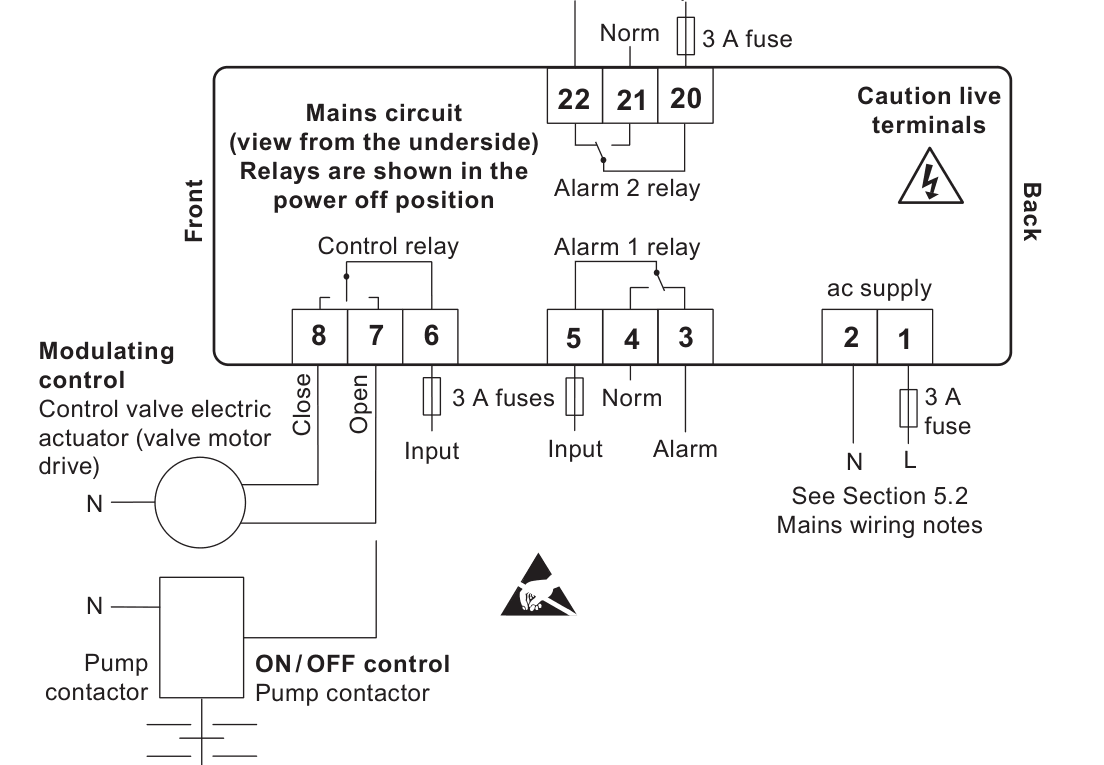
Terminal connections are identified on the terminal plugs. Fit fuses in all live conductors, including the live L/L1 conductor shown in the supply diagrams, and maintain double or reinforced insulation between hazardous live mains or relay circuits and the safety extra-low-voltage circuits. Wiring diagrams show relays and switches in the power-off position.
Figure 3. Mains circuit, control relay, alarm relay and fuse arrangement. View is from the underside; relay contacts are shown power off.
5.3 Signal wiring and functional earth
An earth loop can be created if a wire or screen connects two earth points at different potentials. Follow the diagram so that each screen is connected to earth at one end only. The earth terminal is a functional earth, not a protective earth. LC2250 has double insulation and does not require a protective earth for shock protection, but the functional earth must be connected to a clean local earth so that it can drain electrical interference and meet EMC requirements.
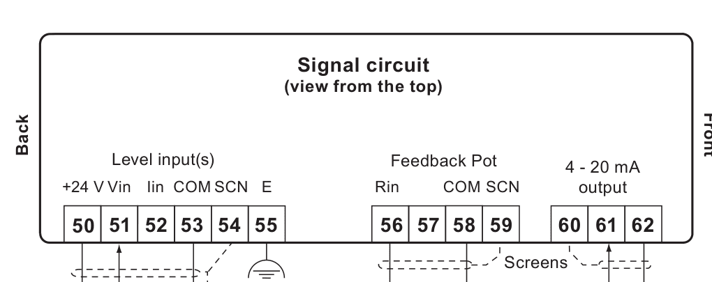
Figure 4. Signal circuit viewed from the top. Level input terminals are 50-55, feedback potentiometer terminals are 56-59 and the 4-20 mA output terminals are 60-62.
5.4 Probe and transmitter wiring
The maximum cable length for all transducers is 100 m. When a capacitance probe and preamplifier are used, select the correct sensitivity on the preamplifier in accordance with its own installation instructions. Do not connect terminal 54 to any other earth. The resistance from the probe body to the pipework or boiler shell must be less than 1 ohm. Connect the E functional-earth terminals to a clean local earth in the panel.
The level output from an LP20 capacitance probe with a PA20 preamplifier may be daisy-chained to more than one instrument. Each receiving instrument must accept a 1-6 Vdc signal; only one instrument needs to provide the nominal 24 V supply for the probe. For a PA420 or other 4-20 mA level transmitter, use the wiring appropriate to a loop-powered or self-powered transmitter and connect its screen to the clean local earth as shown.
The source wiring example shows LC2250 connected in a compatible controller chain with LC2200, LC2300, LC2500 and LT2010. These references describe the connection example only; they are not LC2250 variants or products covered by this page.
The UL version of the preamplifier and capacitance probe must be wired using the supplied flying leads and the associated preamplifier instructions. Do not treat the figure as a substitute for the probe or preamplifier installation instructions.
6. Commissioning
All commissioning is performed from the front panel. Entering commissioning mode stops normal control: the control relay or 4-20 mA output stops the valve, or the pump is switched off. Alarm relays continue to operate. Select End to return to normal control.
If no button is pressed for more than five minutes, the controller returns to run mode and an error occurs. Incomplete calibration may leave the controller unable to provide correct control. LC2250 has no battery; programmed settings are retained in non-volatile flash memory and are written after a parameter is changed and OK is pressed.
6.1 Manual test buttons
Button
Function
AL
Tests the alarm relays and external circuits in run or commissioning mode.
Valve close
In commissioning mode only, closes the valve under proportional control.
Valve open / pump on
In commissioning mode only, opens the valve under proportional control or switches on the pump under pump control.
OK
Held for five seconds to enter commissioning mode and used to enter parameters or digits when they are flashing.
Test buttons are not available while a parameter is being edited. When released, the controller returns to the end of the commissioning menu.
6.2 Access and quick set-up
Only qualified and trained personnel should have access to the commissioning passcode. Remove the passcode section from the guide after commissioning and keep it in a secure, access-controlled location.
The quick set-up accepts factory defaults and is suitable only when those defaults have not been changed. Confirm the defaults in the programming table and apply local regulations, boiler guidance and the boiler manufacturer's recommendations before accepting settings.
Parameter
Action
Lhi
Set the boiler or tank water level to the top of the gauge glass (100%) and press OK.
Llo
Set the water level to the bottom of the gauge glass (0%) and press OK. The water level must remain visible in the gauge glass.
CtL = on/oFF
Select for on/off control with high- and low-level alarms.
CtL = PrO
Select for modulating control. Calibrate PhI with the valve fully open and PLo with the valve fully closed.
For correct operation, calibrate the level input and, where applicable, the feedback potentiometer. Test the complete system after commissioning.
6.3 Full commissioning menu
Choose the input type for the installed level transducer: 1-6 V for the documented capacitance arrangement or 4-20 mA for a transmitter. The minimum conductivity when using the documented capacitance arrangement is 5 µS/cm or 5 ppm.
Menu item
Purpose and available setting
Input Select
Selects 1-6 V or 4-20 mA.
Input Filter
Selects 2, 8 or 16 seconds of level-signal damping. Excessive delay can cause instability.
Input Alarm
Turns the out-of-range alarm on or off.
Alarm 1 and Alarm 2 Select
Sets each alarm as high or low.
Alarm level percentage
Sets each alarm level as a percentage of the gauge glass. Hysteresis is fixed at 5%.
Alarm Filter
Enables an 8-second delay for both alarms to reduce frequent switching in turbulent conditions.
Alarm Latch
With latch off, an alarm operates until the level recovers. With latch on, it continues until reset with the alarm reset or commissioning passcode.
Retransmit
Selects 4-20 mA or 0-20 mA retransmission.
Drive type
Selects relay for valve motor drive or retransmit for 4-20 mA when proportional control is selected.
Drive Action
Inverts the output for the actuator, positioner or pump. Select In for fill control, such as a boiler feedtank, or Out for empty control, such as a condensate tank.
Level High / Level Low
Calibrates 100% and 0% of the gauge glass. Set the actual level at the top or bottom of the gauge glass and press OK. The level must remain visible during the low calibration.
Set Point
Sets the point from which the control band is generated; it is commonly, but not always, halfway between minimum and maximum gauge-glass levels.
Control band
Sets the width of the control band as a percentage of the gauge glass.
Control
Selects proportional control or on/off control.
Potentiometer High / Low
For proportional control only, drives the valve fully open or closed so the feedback potentiometer limits can be calibrated.
End
Press OK to end commissioning and resume normal control.
For proportional control, a rising input produces a falling output when In is selected and a rising output when Out is selected. Setpoint and control-band limits interact; consult the boiler manufacturer for recommended level settings. The absolute minimum level must remain visible in the gauge glass. The guide's typical example uses a 0 - 100% gauge range, an 85% high alarm, a 20% control band around a 50% set point, and a 20% low alarm; the control-band limits shown are 40% and 60%.
7. Communications
LC2250 communicates with adjacent compatible Spirax Sarco boiler-house controllers through an infrared link. It passes its parameters as an OEM slave to a product fitted with RS485 and requires no IR set-up or adjustment. Do not cover or obstruct the infrared beam. Position adjacent units within the documented range and working angle.
8. Maintenance
Read the safety information before maintenance. LC2250 requires no special servicing, preventive maintenance or product inspection. Protect the rear of the product from environmental pollutants during installation or maintenance, or carry out the work in a dry, clean environment.
Boiler water level controls and level alarms do require testing and inspection. Follow applicable guidance, including Health and Safety Executive Guidance Notes BG01 and INDG436 where relevant, and the instructions for the complete Spirax Sarco system.
Cleaning
Clean the unit with a cloth dampened with tap water, de-ionised water or isopropyl alcohol. Other cleaning materials may damage the product and invalidate the warranty.
9. Fault finding
Warning: Read the safety information and general wiring notes before fault finding. Hazardous voltages are present. Only suitably qualified personnel may carry out fault finding, and the product must be isolated from the mains before wiring terminals are touched. Relay fuses must be replaced by the manufacturer or an accredited service department.
Most faults occur during installation and commissioning, and wiring is the most common cause. Protect the rear of the product from environmental pollutants while investigating a fault.
Symptom
Checks and action
Display not illuminating
Switch off the mains; check all wiring and external fuses; check that the mains voltage is within specification; then restore power. If the fault remains, return the product for examination and consider mains-borne surges or spikes and a nearby AC power-line protector.
Display 2 flashes approximately every second
Switch off the mains, disconnect all signal wires and switch on again. If the symptom remains, return the product. Otherwise reconnect signal wires one at a time and investigate the wiring, sensors, transducers and associated modules when the fault recurs. The internal supply is cycling because it cannot power up; this is a safety feature.
Product powers up for more than one minute, then switches off
Check that the mains supply is continuous and within limits, measure ambient temperature, and check for excessive load or low input voltage. A resettable thermal cut-out operates when power demand, low mains voltage or ambient temperature is excessive; the supply restarts after the product cools below 65 °C.
Controller does not respond to level changes
Check whether LLo and LHi have both been set to 100%, which can produce a 0% process value. Recalibrate the level inputs.
Incorrect number, letter or symbol displayed
Hold OK for five seconds, confirm that 888 is displayed, then press OK again. Missing segments indicate a display-segment failure that can make readings difficult to interpret.
9.1 Operational error messages
Message
Cause
Action
Power 1
Power was lost during operation.
Remove power, check the wiring and secure supply, then reapply power.
Set up 2
Commissioning mode timed out after five minutes without a button press.
Re-enter commissioning mode if required.
Outrange 3 high
Level input has risen above its product specification.
Measure input current or voltage and correct the signal so it is within specification.
Outrange 4 low
Level input has fallen below its product specification.
Measure input current or voltage and correct the signal so it is within specification.
Alarm 5 1
A high- or low-water alarm has occurred on alarm 1.
Check boiler set-up and operation of the alarm and boiler water-supply systems.
Alarm 6 2
A high- or low-water alarm has occurred on alarm 2.
Check boiler set-up and operation of the alarm and boiler water-supply systems.
Alarm 7 latched
An error or alarm has latched the alarm relay for safety.
Enter commissioning mode and use the correct alarm reset or commissioning passcode after correcting the cause.
10. Programming parameters and default settings
These factory defaults are used by the quick-start procedure. Confirm them before relying on the quick set-up, and adjust them only after the complete boiler or vessel control strategy has been reviewed.
Parameter
Range
Default
Units or note
InS - Input Select
1-6 or 4.20
1-6
Vdc or mA
InF - Input Filter
2, 8 or 16
2
Seconds
InA - Input Alarm
OFF or ON
OFF
Out-of-range alarm
AS1 / AS2 - Alarm Select
Hi or Lo
Hi / Lo
Alarm 1 / Alarm 2
AP1 / AP2 - Alarm percentage
5-100 for high or 0-95 for low
85 high or 20 low
Resolution 1%; percent of gauge glass
ALF - Alarm Filter
OFF or ON
OFF
Applies to both alarms
ALL - Alarm Latch
OFF or ON
OFF
Applies to both alarms
rEt - Retransmit
4-20 mA or 0-20 mA
4-20 mA
Output signal
dr - Drive
rel or ret
rel
Relay or retransmit
ACt - Action
In or Out
In
Reducing with rising level
SP - Set Point
3-97
50
Percent; interactive with control band
Cb - Control band
5-100
20
Percent; interactive with setpoint
CtL - Control
On/Off or Pro
Pro
Control mode
11-12. Appendix: data registers and menu map
Data registers
Register data is a 16-bit integer with the most significant byte transmitted first.
Register
Parameter
0
4 - identity
1
Process variable (PV) - water level (%)
2
Set point (SP)
3
Control band (CB)
4
Alarm 1
5
Alarm delay
6
Alarm 2
7-9
Not assigned in the guide's register table
Menu map
The menu provides the following choices: input select 1-6 V or 4-20 mA; input filter 2, 8 or 16 seconds; input alarm off or on; high or low selection and percentage for each alarm; alarm filter off or on; alarm latch off or on; 4-20 mA or 0-20 mA retransmission; relay or retransmit drive type; In or Out drive action; level high and low calibration; setpoint; control band; proportional or on/off control; potentiometer high and low calibration; and End.
Reference: This installation and maintenance section is condensed from IM-P402-130 EMM Issue 9. Preserve the source guide as the controlling document for site-specific safety assessment, wiring, commissioning and maintenance.