IT
IT Immersion Tubes
IT immersion tubes distribute condensate into boiler feedtanks through austenitic stainless-steel tubes with sandwich flanges for ANSI 150 or EN 1092 PN16 arrangements, with documented gravity and pumped capacity data for IT100 to IT400.
IT immersion tubes for boiler feedtank condensate distribution
Spirax Sarco IT immersion tubes are condensate distributors designed to introduce returned condensate into a boiler feedtank in a controlled, compact arrangement. They can be connected directly to the condensate pipeline, making them suitable where the tank design needs a dedicated inlet that distributes the flow below the water surface. The product family is documented as an alternative to traditional sparge pipes for both new and retrofit feedtank projects.
An immersion tube is a practical part of a larger feedwater arrangement rather than a replacement for the tank, condensate return pipework or the controls around them. Its performance depends on the selected DN, immersion length, condensate condition and the way the feedtank is constructed. The tank must be adequately constructed and braced before an IT tube is installed, particularly when the installation is a retrofit or when pipework changes may introduce external loads.
What an IT immersion tube does
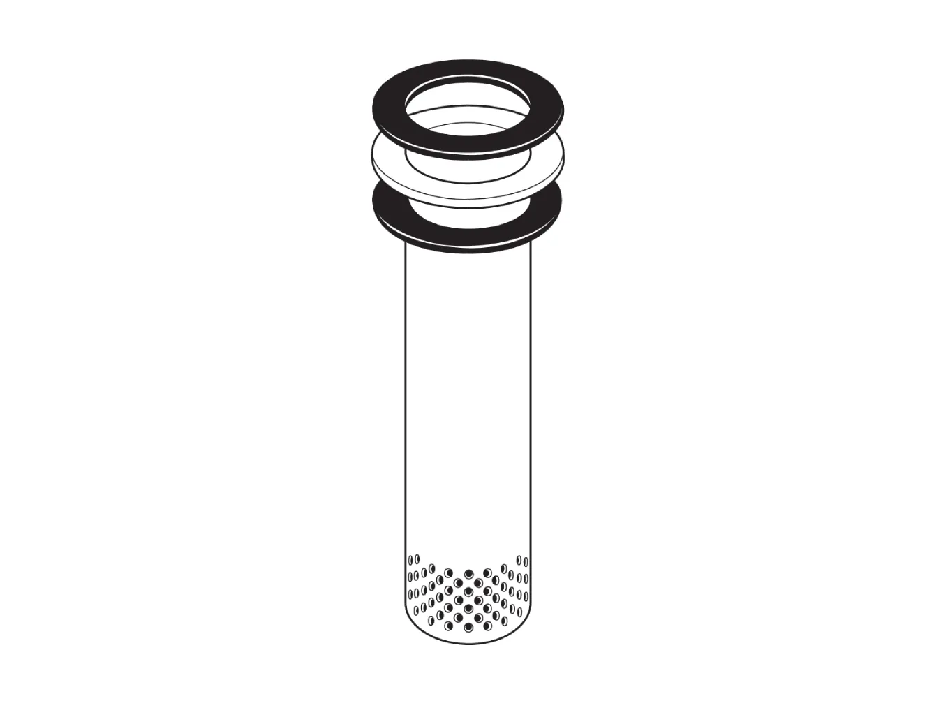
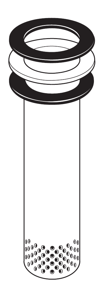
Returned condensate enters the immersion tube and is distributed through the pattern of holes at its lower end. Each tube has a hole pattern suited to the stated capacity. This provides a more orderly tank entry than a traditional sparge-pipe arrangement and can reduce problems associated with vibration, rusting and waterhammer. The result is a compact connection that keeps the distribution point inside the tank while leaving the tank designer to confirm the supporting structure and connected pipework.
The tubes may be used in direct condensate service or as part of a separately documented flash-condensing de-aerator arrangement. IT100 is not suitable for use with the mixing unit described in the source literature. Where a mixing arrangement is being considered, the tube must be selected against the guidance for that complete arrangement rather than against the direct-condensate capacity table alone.
This distinction matters when a project combines returned condensate with other feedwater streams. A direct IT installation distributes condensate; it does not by itself establish the mixing, venting or gas-release performance of a complete feedtank system. For wider system planning, review the available boiler feedtank systems and confirm how the condensate return, make-up water, vent and feedwater routes will be arranged.
Choosing a Spirax Sarco IT immersion tube
The documented types are IT100, IT150, IT200, IT250, IT300 and IT400. The model designation combines the IT prefix, the nominal DN and the immersion-tube length in millimetres. For example, IT250-1600 identifies a DN250 tube with an immersion length of 1,600 mm measured from the underside of the flange; the source gives a 2,000 mm deep tank as the suitable tank example for that length.
Lengths are available to suit TM metric feedtanks, and other lengths can be made to special order. The length should therefore be checked against the actual tank connection, water level, internal clearances and the required submerged position. A model code alone is not enough to confirm fit: the tank nozzle, flange arrangement, condensate return main and support details must all be reviewed before ordering.
For use without a mixing unit, the technical data separates gravity condensate containing 5% flash steam from pumped condensate. Across the documented IT100 to IT400 range, the listed gravity capacities run from 1,015 to 16,255 kg/h and the listed pumped capacities run from 2,500 to 50,000 kg/h. These are selection data for the stated conditions, not a universal flow guarantee. If the flash-steam content changes, the source states that the capacity may be determined pro rata; at 10% flash, the capacity is half the value shown.
A useful first sizing rule is to select an immersion tube at least one DN larger than the condensate return main. The final selection still needs the real condensate load and the correct operating arrangement. Confirm whether the flow is gravity-fed or pumped, account for flash steam where applicable, and check whether the selected IT type and length match the feedtank connection. The full capacity and dimensional tables are retained below in the technical information section.
Construction, flange and service limits
The tube is made from austenitic stainless steel and the documented gaskets are silicone rubber. An integral inside bolt-circle sandwich flange is designed to suit ANSI 150 or EN 1092 PN16 flange arrangements. These flange references describe the connection fit; they should not be read as a higher pressure rating for condensate service.
The stated IT limiting condition is a PN2.5 rating, suitable for condensate up to 1 bar g and 120 °C. Projects outside those documented conditions need a separate suitability review. Check the maximum pressure and temperature of the returning condensate, the tank connection design and any local regulatory constraints before the tube is committed to the system.
Because the tube is installed through the tank top and remains connected to hot condensate pipework, the surrounding design must allow inspection, safe isolation and suitable access. Pipework supports should prevent the connected system from imposing avoidable loads on the tank or the sandwich flange.
Tank integration and installation planning
The recommended position is in the middle of the top of the feedtank. With an existing flange, the tube is designed to pass through an aperture to the documented BS 1600 Schedule 40 dimensions. The sandwich flange matches the raised-face diameter of the compatible flange, and gaskets are installed above and below the sandwich flange. The exact nozzle and blind-flange construction remains a tank-design responsibility.
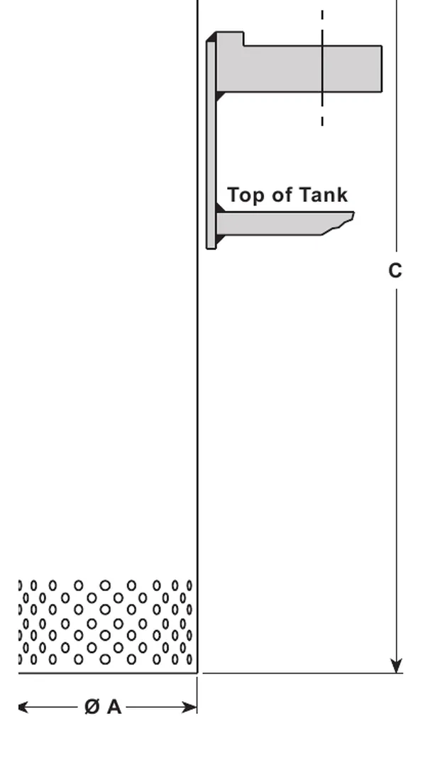
For a new installation, incorporate a specific tank connection using the project's approved tank connection documentation. The connection should be aligned with the bolt-hole centre and checked for adequate flatness, reinforcement and clearance. The technical drawing shows the relationship between the immersion tube, gasket, tank top and the A, B and C dimensions; the native dimensions/weights table below should be used for the selected model and length.
A vacuum breaker is essential on the condensate return main near the immersion tube. The source suggests considering a VB14 vacuum breaker. The preferred position is close to the tube; an alternative position is near the elbow when the pipe arrangement makes that more practical. This requirement should be included in the condensate-return design rather than treated as an optional page accessory.
When the wider package also needs direct steam injection for feedwater heating, compare the tube arrangement with the available steam injectors. When the project is recovering heat from blowdown or flash steam before it reaches the tank, review boiler heat recovery systems as a separate system-selection step. If the returned condensate route also needs receiver or pumping decisions, review condensate recovery systems. These links provide adjacent planning routes; they do not change the IT product boundary.
Ordering checks for IT
Confirm the IT type, DN and required immersion length in millimetres.
Confirm whether the condensate is gravity-fed or pumped and establish the flash-steam condition used for sizing.
Check the return-main DN against the general one-DN-larger sizing rule and verify the full capacity table.
Confirm the flange standard, tank aperture, sandwich-flange arrangement and the two gasket positions.
Verify that the feedtank is adequately constructed and braced and that the pipework is independently supported.
Include the nearby vacuum breaker in the condensate return design and confirm safe access for installation.
For a Spirax Sarco IT immersion tube quotation, provide the selected type, DN, length, flange standard, condensate duty and tank connection details together. This gives the project team enough information to check the documented limits and identify any tank-specific connection work before supply.
Description
Spirax Sarco immersion tubes may be connected directly to the pipeline to distribute condensate into feedtanks. They may also be used with a mixing unit to form a flash-condensing de-aerator head; this use is not applicable to the IT100 unit.
A flash-condensing de-aerator arrangement is described in separate literature. Immersion tubes offer a much neater solution than traditional sparge pipes and can reduce problems associated with them, including vibration, rusting and waterhammer. They are suitable for new and retrofit applications where the feedtank is adequately constructed and braced.
Available types
Available types are IT100, IT150, IT200, IT250, IT300 and IT400 with an integral inside bolt-circle sandwich flange to suit ANSI 150 or EN 1092 PN16. Lengths suit TM metric feedtanks; other lengths can be made to special order.
Immersion tubes are designated by IT followed by DN followed by the immersion-tube length in mm. For example, IT250-1600 is DN250 and is 1,600 mm long from the underside of the flange. It is suitable for a 2,000 mm deep tank.
Capacity - when used without a mixing unit
IT type | DN | Gravity condensate with 5% flash | Pumped condensate |
|---|---|---|---|
IT100 | 100 | 1 015 | 2 500 |
IT150 | 150 | 2 285 | 5 000 |
IT200 | 200 | 4 065 | 10 000 |
IT250 | 250 | 6 350 | 20 000 |
IT300 | 300 | 9 145 | 30 000 |
IT400 | 400 | 16 255 | 50 000 |
For other quantities of flash steam, capacity may be determined pro rata. For 10% flash, capacity is half the value shown.
As a general rule, the size of an immersion tube should be at least one DN larger than the condensate return main.
Important note: The table is valid for condensate where the flash-steam content is considered. When sizing an immersion tube used with a de-aerator-head arrangement, use the separate guidance for that complete arrangement. No mixing unit is made to suit IT100.
Limiting conditions
PN2.5 rating. Suitable for condensate at up to 1 bar g, 120 °C.
Materials
No. | Part | Material |
|---|---|---|
1 | Immersion tube | Austenitic stainless steel |
2 | Gaskets | Silicone rubber (colour may vary) |
The tank-connection drawing labels a 3 mm dimension at the gasket and a 6 to 10 mm dimension at the immersion tube. Use the drawing with the table when checking the tank connection.
Installation
We recommend that the immersion tube is positioned in the middle of the top of the tank.
The immersion tube can be fitted to a boiler feedtank by the following methods:
Using an existing flange. The immersion tube is designed so that it can pass through an aperture with dimensions according to BS 1600 Schedule 40. The sandwich flange is equal to the raised-face diameter of the flange for which it is suitable. Gaskets are placed above and below the sandwich flange.
On new installations. A specific connection should be incorporated as described in separate literature.
It is essential that a vacuum breaker is fitted to the condensate return main near to the immersion tube. Consider the use of a Spirax Sarco VB14 vacuum breaker.
How to order - example
Immersion tube IT150-950 in austenitic stainless steel to suit DN150, PN16 flanges.
Silicone rubber gaskets to suit DN150, PN16.
Dimensions and weights
Approximate dimensions in mm and weights in kg.
Model | A | B PN16 | B ANSI 150 | C | Weight |
|---|---|---|---|---|---|
IT100 - 950 | 114 | 162 | 157 | 950 | 7 |
IT100 - 1200 | 114 | 162 | 157 | 1200 | 9 |
IT100 - 1600 | 114 | 162 | 157 | 1600 | 11 |
IT150 - 950 | 168 | 212 | 216 | 950 | 10 |
IT150 - 1200 | 168 | 212 | 216 | 1200 | 12 |
IT150 - 1600 | 168 | 212 | 216 | 1600 | 16 |
IT200 - 950 | 219 | 268 | 270 | 950 | 13 |
IT200 - 1200 | 219 | 268 | 270 | 1200 | 16 |
IT200 - 1600 | 219 | 268 | 270 | 1600 | 21 |
IT200 - 2000 | 219 | 268 | 270 | 2000 | 28 |
IT250 - 1200 | 273 | 320 | 324 | 1200 | 20 |
IT250 - 1600 | 273 | 320 | 324 | 1600 | 27 |
IT250 - 2000 | 273 | 320 | 324 | 2000 | 35 |
IT300 - 1200 | 323 | 378 | 381 | 1200 | 24 |
IT300 - 1600 | 323 | 378 | 381 | 1600 | 32 |
IT300 - 2000 | 323 | 378 | 381 | 2000 | 42 |
IT400 - 1200 | 406 | 490 | 470 | 1200 | 29 |
IT400 - 1600 | 406 | 490 | 470 | 1600 | 39 |
IT400 - 2000 | 406 | 490 | 470 | 2000 | 51 |