Compare the wider regulator family
Return to the wider pressure reducing and surplussing valve route when you need to compare 25P with DP27, BRV, LRV or sanitary pressure control options.

Control systems > Pressure reducing valves
25P Pilot Operated Pressure Reducing Valve
25P is a self-actuated pilot-operated pressure regulator for steam, published from ½" to 4" with a 6" size. Cast iron or cast steel bodies, NPT or ANSI flanged connections and three colour-coded pilot springs cover downstream pressures from 3 to 250 psi.
Quick facts
The Spirax Sarco 25P is a self-actuated pilot-operated pressure regulator for steam services. It reduces steam from a high supply pressure to the most efficient operating pressure of the equipment it serves, and protects that equipment from dangerously high pressures. The regulator is published from ½" to 4" in the main technical information sheet, with a 6" size covered by a separate sheet, in screwed NPT and flanged ANSI connection options and in cast iron or cast steel construction.
Within the Spirax Sarco range the 25P belongs to the pressure reducing and surplussing valves group, which covers regulators used to hold a controlled downstream pressure in steam and industrial fluid systems. The 25P is a pilot-actuated, diaphragm-operated design rather than a direct-acting one: a small pressure pilot controls a separate main valve, so a compact pilot can control a much larger valve than a spring-and-diaphragm actuator of the same physical size could manage.
Downstream pressure is fed back through an external sensing line to the pressure pilot. The pilot compares that feedback with its spring setting and adjusts the opening of the main valve so that the set pressure is held as the load changes. The sensing line connection on the regulator is ¼" NPT.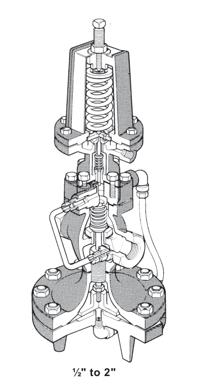
On ½" to 4" sizes the pilot is bolted directly to the regulator body. On the 6" size the pilot is externally mounted. In both cases the main valve is single-seated with hardened stainless steel trim, and the regulator can close tight to ANSI/FCI 70-2 Class IV shut-off when steam is not required.
Shut-off capability has to be read together with the size. The ½" to 4" 25P is described as capable of dead-end shut-off, so it can hold a closed downstream system. The 6" 25P meets the Class IV shut-off specification but is not suitable for dead-end service, so a 6" installation needs a positive isolation method wherever the downstream system can be shut in completely.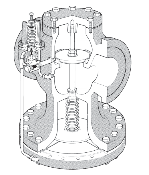
The controlled downstream pressure is set by the pilot valve spring, and three colour-coded springs are available:
The ranges overlap deliberately, so a duty close to the boundary between two springs can usually be met by either. The spring is selected on the required downstream pressure rather than on the supply pressure, and it has to be fixed before the regulator is ordered.
Capacity is published as pounds of saturated steam per hour for each nominal valve size at a given inlet and outlet pressure. A second capacity table covers the reduced-port "S" versions, which are used where lower steam velocities are required. The full-port Cv factors are 3.48 for ½", 6.5 for ¾", 10.5 for 1", 14 for 1¼", 20 for 1½", 35 for 2", 56 for 2½", 74 for 3", 115 for 4" and 280 for the 6" size. The reduced-port versions have lower Cv factors, from 1.16 for ½"S" up to 156 for 6"S".
Sizing is worked from the inlet pressure, the required downstream pressure and the steam flow at the duty point, using the sizing and selection chart. The published capacities are based on a regulation accuracy of 1 psi and assume pipe sizes that keep steam velocities reasonable, so the pipe sizing chart has to be checked alongside the regulator selection rather than afterwards.
Body material and operating pressure are linked in the sizing data: cast steel construction is required for service above 250 psi g.
Where a different pressure reducing valve suits the duty better, the same range covers other options. The DP27 pressure reducing valve is another pilot-operated regulator, in ductile iron construction, and the BRV2S direct acting pressure reducing valve is a compact direct-acting option for steam and compressed air duties. The 25P remains the pilot-operated cast iron or cast steel choice for larger steam duties.
The regulator body and cover are cast iron to ASTM A 126 CL B or cast steel to ASTM A216 Gr WCB. The main valve head, main valve seat and valve return spring are stainless steel, and the main diaphragm is a two-ply stainless steel element. Cover and body gaskets are graphite on the larger sizes and copper-clad on ½" to 2", and the pilot gasket is graphite.
Transmission tubing follows the body material. Cast iron regulators are supplied with copper tubing and brass fittings as standard, and cast steel regulators with stainless steel tubing. Stainless steel transmission tubing is also available as a spare part kit for each size where a higher temperature or a different requirement makes it necessary. The maximum temperature for stainless steel transmission tubing is 600 °F (316 °C).
Connection options are screwed NPT and flanged ANSI 125 or 150 for cast iron bodies, and NPT with ANSI 250 or 300 flanges for cast steel bodies. ANSI 150 and ANSI 250 flanged options are also listed, with the ANSI 250 option excluding the 2" size. Pressure and temperature limits are published as separate envelopes for cast iron and cast steel bodies, plotted against the steam saturation curve. The shaded region of each chart marks the area in which the product should not be used; operation in that region requires stainless steel transmission tubing to be fitted.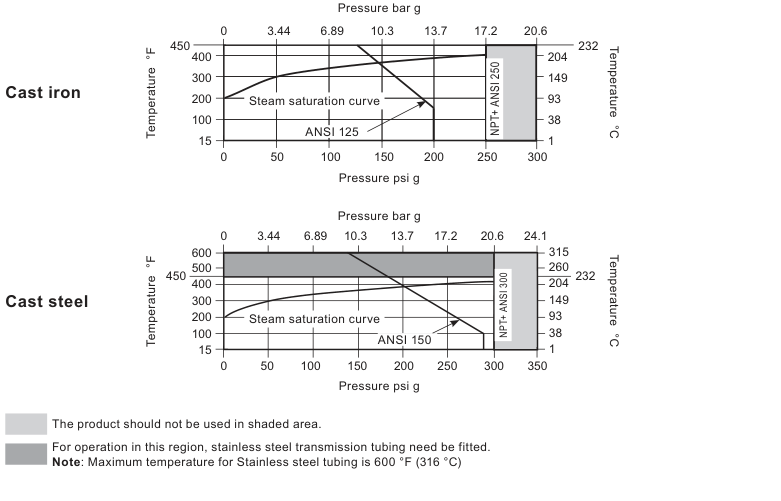
The regulator is installed in a horizontal line with a suitable bypass and isolating valves, so that it can be serviced without shutting the plant down. A steam trap is installed upstream to prevent condensate from reaching the regulator, and both the trap and the regulator are protected with a strainer; on the 6" size the published recommendation is a strainer separator set.
The pressure sensing line must be taken from a straight section of the downstream piping at least 10 pipe diameters from the nearest fitting. That distance is a functional requirement, not a preference: a sensing point close to a bend, a reducer or another fitting reads a distorted pressure, and the regulator will then hold the wrong downstream pressure. The sensing line is part of the installation rather than an accessory, and its route and material have to be planned with the pipework.
Weight is worth checking at the layout stage. A ½" cast iron regulator weighs approximately 32 lb (14.5 kg) and a 4" cast iron regulator approximately 284 lb (129 kg), with the cast steel versions slightly heavier at each size. The 6" size weighs approximately 595 lb (270 kg), so it normally needs its own pipe support.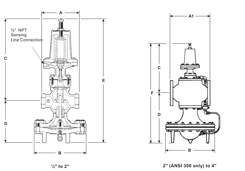
The 25P is maintained against a published installation and maintenance instruction, a copy of which is supplied with each regulator; the ½" to 4" sizes refer to IM-P717-06-US and the 6" size to IM-3-000-US. Available spare parts are listed separately for each size group.
Full technical data, materials lists, dimensions and weights for the ½" to 4" range are given in the technical information sheet, and the 6" size has its own sheet. Selection and sizing data for the whole 25P range, including the reduced-port versions, is published in the sizing and selection chart. The downloadable documents on this page are the current issue of each of these, and they remain the reference for installation, commissioning and maintenance work.
Confirm the following before the regulator is specified:
Checking these points against the current technical data before ordering avoids the two most common selection errors: a regulator sized for the wrong flow, and a spring that cannot reach the required downstream pressure.
A 25P selection usually sits inside a wider pressure station decision that also includes protection, monitoring and adjacent control hardware.
Return to the wider pressure reducing and surplussing valve route when you need to compare 25P with DP27, BRV, LRV or sanitary pressure control options.
Move into the broader control systems range when the project also needs control valves, self-acting temperature control or actuator-led modulation.
Review gauges and temperature instruments when commissioning and ongoing pressure verification are part of the same station design.